USTC/Demonstration
From 2007.igem.org
(Difference between revisions)
m |
m |
||
| Line 6: | Line 6: | ||
* shows that wires can cross and branch off (without interference); | * shows that wires can cross and branch off (without interference); | ||
* is loaded on two plasmids, [http://partsregistry.org/Part:BBa_I732998 pSB1A3-I732998] and [http://partsregistry.org/Part:BBa_I732999 pSB1A3-I732999] , and transformed into Top10 strain in practice; | * is loaded on two plasmids, [http://partsregistry.org/Part:BBa_I732998 pSB1A3-I732998] and [http://partsregistry.org/Part:BBa_I732999 pSB1A3-I732999] , and transformed into Top10 strain in practice; | ||
| - | * accepts aTc and AHL | + | * accepts aTc and AHL signals as inputs; |
| - | * is expected to output the results as the truth table shown in Figure | + | * produce RFP and GFP signals as outputs; |
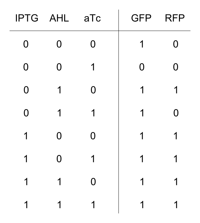
| + | * is expected to output the results as the truth table shown in Figure 2. | ||
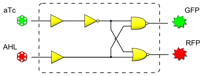
[[Image:DemonstrationLogic.png|thumb|512px|left|'''Figure 1''' The logic diagram of the demo system.]] | [[Image:DemonstrationLogic.png|thumb|512px|left|'''Figure 1''' The logic diagram of the demo system.]] | ||
Revision as of 18:36, 21 October 2007
An actual demonstration is decided to show the ability of our method.
This demo system
- is designed as simple as possible, without no "cool" logic function;
- includes all the three logic gates, which form into a three-level logic circuit;
- shows that wires can cross and branch off (without interference);
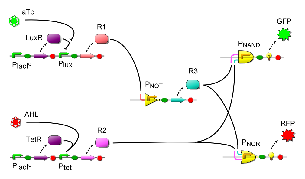
- is loaded on two plasmids, pSB1A3-I732998 and pSB1A3-I732999 , and transformed into Top10 strain in practice;
- accepts aTc and AHL signals as inputs;
- produce RFP and GFP signals as outputs;
- is expected to output the results as the truth table shown in Figure 2.


