Edinburgh/DivisionPopper/Design
From 2007.igem.org
Luca.Gerosa (Talk | contribs) (→Proof of Concepts) |
Luca.Gerosa (Talk | contribs) |
||
| Line 141: | Line 141: | ||
'''The Biology Processes:''' | '''The Biology Processes:''' | ||
| - | + | We used the Edinburgh Pathway Notation, a state transition graphical notation to express the biological processes of the Division PoPper. The details regarding the notations can be found in the paper | |
| - | + | ||
[http://www-bm.ipk-gatersleben.de/stable/php/journal/articles/pdf/jib-36.pdf A Graphical Notation to Describe the Logical Interactions of Biological Pathways]. | [http://www-bm.ipk-gatersleben.de/stable/php/journal/articles/pdf/jib-36.pdf A Graphical Notation to Describe the Logical Interactions of Biological Pathways]. | ||
| + | |||
| + | {| border="1" cellpadding="20" cellspacing="0" | ||
| + | !Diagram | ||
| + | !Explanation | ||
| + | |- | ||
| + | |[[ | ||
| + | Image:PoPperEPN.jpg|550px]] | ||
| + | |This EPN Diagram explains which are the state configuration of the Division PoPper construct when a Reporter Protein is placed downstream the device. The Division Event state explains which state transitions occur when a division happens. The gray boxes represent the state (active, inactive) of the coding regions and promoter regions associated to TetR and LambaCR production. The white boxes represent the proteins. | ||
| + | |- | ||
| + | |} | ||
Revision as of 16:12, 24 September 2007
MENU : Introduction | Background | Applications | Design&Implementation | Modelling | Wet Lab | Synthetic Biology Approach | Conclusions
In the Design section we define the architecture (design), the biology elements (implementation) and the mechanisms (dynamics) of the device. According to the [http://partsregistry.org/cgi/htdocs/AbstractionHierarchy/index.cgi abstraction levels hierarchy], we propose the view of the Division PoPper at the level of device, parts and DNA. Regarding to the dynamics we explain which are the biological processes involved and how they cooperate in defining the behaviour of the device. The logic design and implementation phases have been decoupled.
Contents |
Design
In this section we explain which are the functional components of the device and how they are connected logically and physically. The view on the device is given following the [http://partsregistry.org/cgi/htdocs/AbstractionHierarchy/index.cgi abstraction hierarchy] proposed in the Registry of Parts.
| Device abstraction level of the Division Counter |
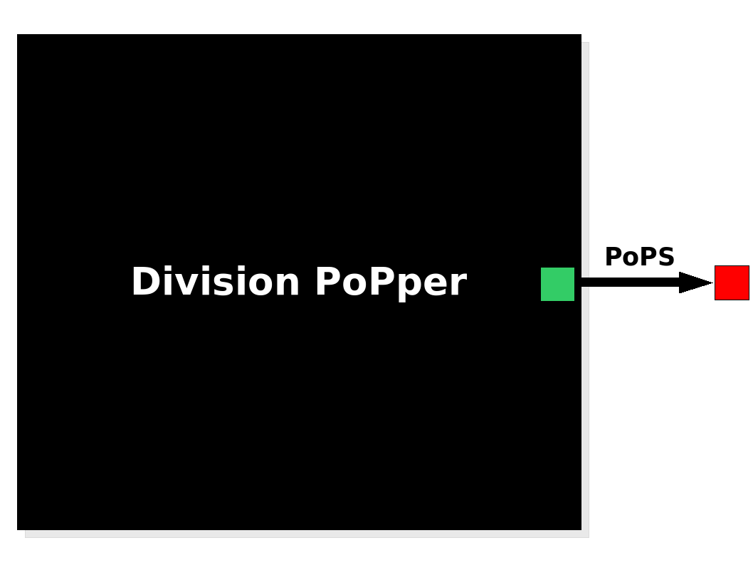 The Division PoPper device generates an input in the form of PoPS signal. The Division PoPper device generates an input in the form of PoPS signal.
|
Device abstraction level
The Division PoPper is a device, because it is a functional element that can be further compose with other devices by the use of a standard PoPS signal. The device has no formal input but its behaviour is triggered by an "external" stimulus: the cell division. The output is a PoPS signal that is supposed to be always zero (not considering leaking issues in the promoters) apart when a cell divion happens. In this case the device generates a pulse: the PoPS signal reaches a non-zero level for a period of time, returning to zero value afterward. The function of the device is simple: to inform a downstream device that a division happened by sending a pulse signal. We suggests some systems configuration in the Applications section.
| Part abstraction level (Design) |
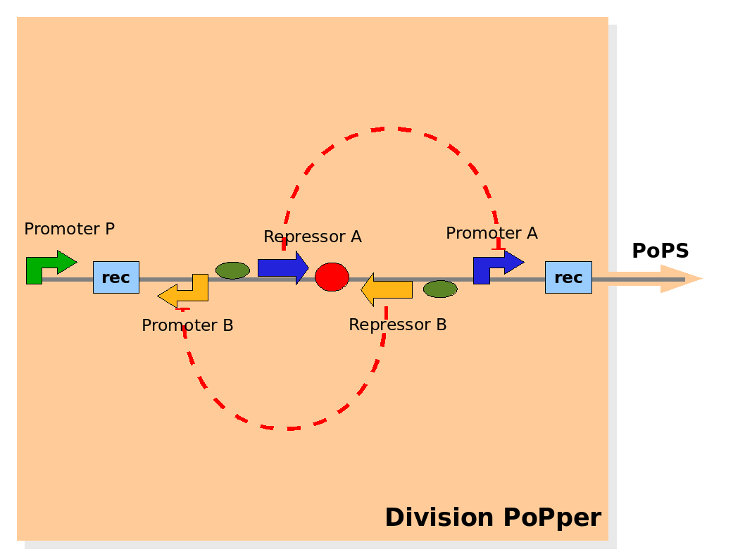 Design of the part structure in the Division PoPper device. Design of the part structure in the Division PoPper device.
|
Part abstraction level
At the level of part abstraction we define the functional parts of the device: regulatory regions, coding regions, terminators and so on. Instead of proposing directly the actual biological entities, we propose here a logic view. Strictly speaking, we defines entities by their attributes and abilities, but without mapping them to real biological objects. This is done then in the Implementation section below. The motivation is to separate the functional design from the realization choices.
The Division PoPper functional parts are:
- two recombinase site sequences: Rec.
- a promoter A that can be repressed by protein A: promoter A.
- a coding region for protein A: repressor A.
- a promoter B that can be repressed by protein B: promoter B.
- a coding region for protein B: repressor B.
- a promoter P that is constitutively active (expressing).
The functional ability that these entities should have are:
- the region between Rec recombinase site sequence is flipped (reversed horizzontally and vertically) at each cell division.
- the protein A and protein B degredation rate should be fast enough to degrade them rapidely when not expressed.
- the protein A and protein B effects on (respectively) the promoter A and B expression capacity should be strong.
- promoter P should be strong in is constitutive expression.
The physical configuration:
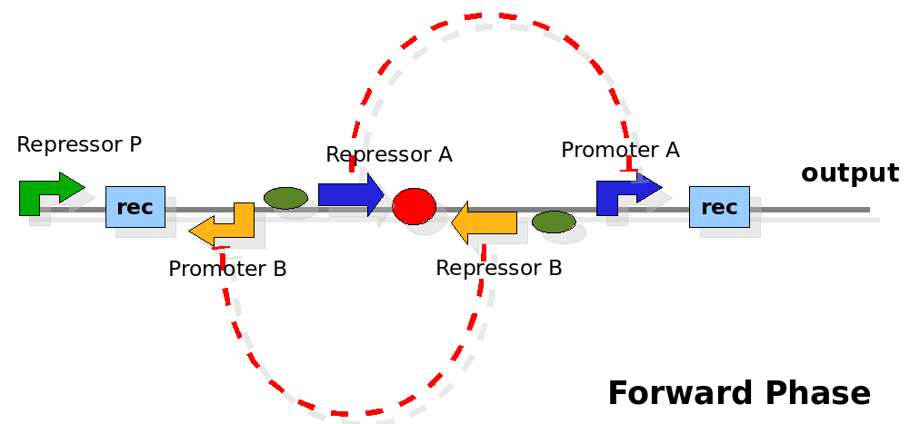
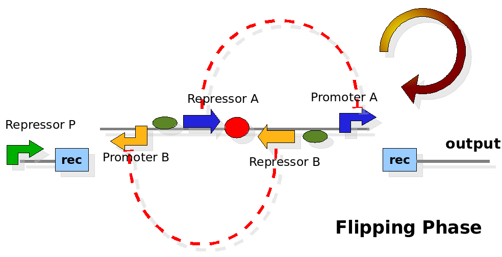
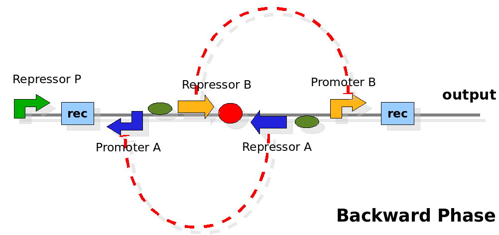
The design relies on the alternate expression of the two strands of the DNA segement in between the Recombinase sites. Promoter P is placed outside the "flipping region" and controls its downstream region in the upper strand. The output of the device is given by the PoPS activity on the upper strand downstream the last recombinase site. Since the region in between the recombinase sites flips, the output is controlled alternatively by the two DNA strands. In one strand the parts sequence is: repressor A, terminator, Promoter A. In the other the sequence is: repressor B, terminator, Promoter B.
The dynamics:
As cell division occurs, DNA enclosed by two inverted Rec sites is reversed. Initially the device is in the configuration with Repressor A and Promoter A on the upper strand. There is no Repressor A presents in the cell so Promoter A produces a constant PoPS output. As time passes, Repressor A production is turned on and 'turns off' Promoter B. Meanwhile Repressor B is no produced and degrades so that, at the next division, Promoter B can produce PoPS output and the process repeats. This mechanism can be seen as the sequence of three phases: Forward, Flipping and Backward. We explain for each phases the dynamics:
Implementation
In the previous section we define which functional components are needed at the level of parts. In this section the members with biology competences evaluate the design and identify the actual biological parts that can be used. Further on the DNA abstraction level details are proposed.
| Part abstraction level (Implementation) |
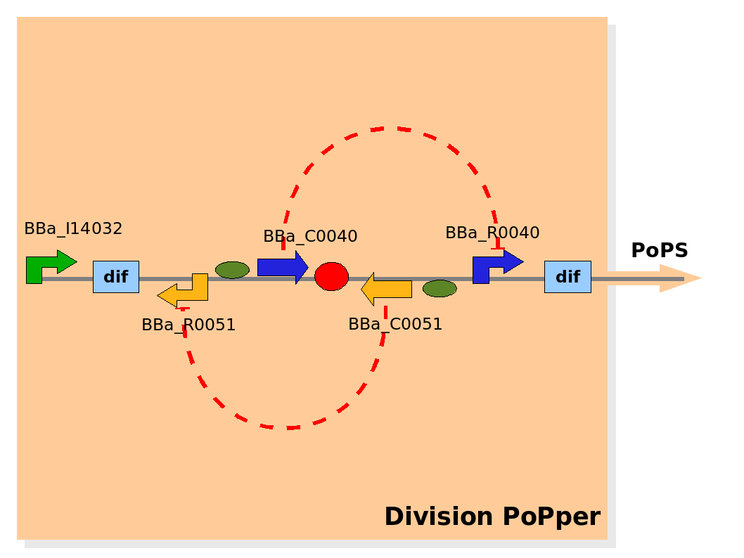 Implementation of the part structure in the Division PoPper device. Implementation of the part structure in the Division PoPper device.
|
Part abstraction level
The Division PoPper parts are:
- two Dif recombinase sites (design: Rec).
- Tet promoter (design: promoter A).
- TetR repressor (design: repressor A).
- CLambda promoter (design: promoter B).
- CLambda repressor (design: repressor B).
- Lac promoter (design: promoter P).
The Registry of Standard Parts contains already some of the elements we need, for the others we constructed and added their Biobricked version.
The Division PoPper parts registry entries are:
- two Dif recombinase sites: [http://partsregistry.org/Part:BBa_I742101 BBa_I742101],[http://partsregistry.org/Part:BBa_I742102 BBa_I742102]
- Tet promoter:[http://partsregistry.org/Part:BBa_R0040 BBa_R0040]
- TetR repressor:[http://partsregistry.org/Part:BBa_C0040 BBa_C0040]
- CLambda promoter:[http://partsregistry.org/Part:BBa_R0051 BBa_R0051]
- CLambda repressor:[http://partsregistry.org/Part:BBa_C0051 BBa_C0051]
- Lac promoter:[http://partsregistry.org/Part:BBa_I14032 BBa_I14032]
Click on the links for details. (for the group: codes need to be controlled).
The assumption on the biological elements are:
- The Dif sites flip only once during each cell division
- TetR and ClambdaR are produced and degrade faster than the cell cycle
For this device to work, dif site-enclosed DNA needs to flip but once per division. Like all recombination sites, dif-sites are directional and bacteria uses directly repeated dif-sites to resolve genome dimers. Research shows that this resolution occurs only at septation, and we use this temporal control to inverse a plasmid-kept sequence to induce different functions. For more information look at the Background section.
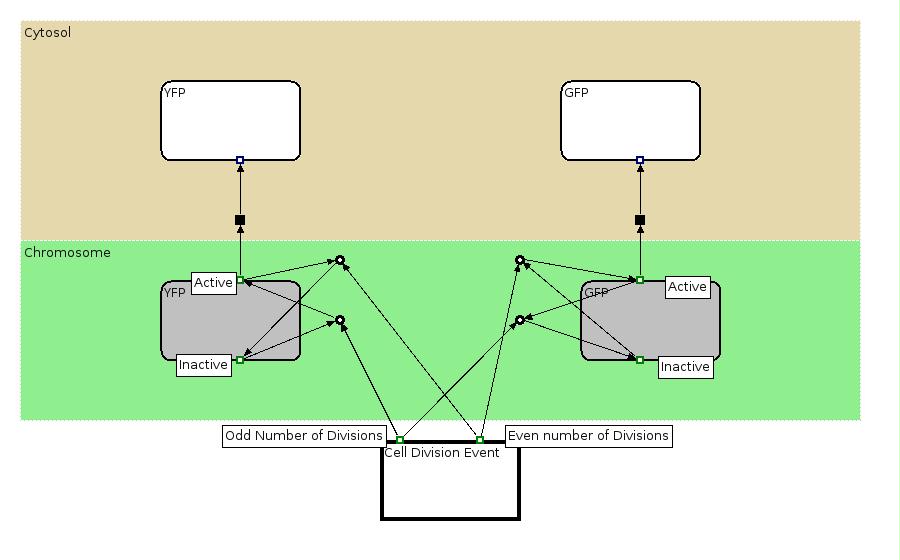
The Biology Processes: We used the Edinburgh Pathway Notation, a state transition graphical notation to express the biological processes of the Division PoPper. The details regarding the notations can be found in the paper [http://www-bm.ipk-gatersleben.de/stable/php/journal/articles/pdf/jib-36.pdf A Graphical Notation to Describe the Logical Interactions of Biological Pathways].
| Diagram | Explanation |
|---|---|
| [[
Image:PoPperEPN.jpg|550px]] | This EPN Diagram explains which are the state configuration of the Division PoPper construct when a Reporter Protein is placed downstream the device. The Division Event state explains which state transitions occur when a division happens. The gray boxes represent the state (active, inactive) of the coding regions and promoter regions associated to TetR and LambaCR production. The white boxes represent the proteins. |
| DNA strands configuration |
 This graph explain on which DNA strand the parts are placed and with which coding direction. This graph explain on which DNA strand the parts are placed and with which coding direction.
|
DNA abstraction level
Details at the level of DNA (for the group:TO DO).
Proof of Concepts
The complex structure of the Division PoPper and the few time we have for the construction of the device in the context of iGEM competition forced us in planning the construction of a simpler construct: the Proof of Concepts. The aim of the Proof of Concepts construct is to test the main assumptions at the basis of the Division PoPper device: the recombinase mechanism is activated only once and at cell division and the time between divisions is enough for repression mechanism to be activate-inactivated. We planned to construct two experiments:
Experiment 1:
This experiment will prove whether or not the DNA between the two dif sites flip at all during cell division. If the a flip occurs, then the direction the promoter operates will be changed and YFP will be expressed. The BioBrick used for YFP expression is [http://partsregistry.org/Part:BBa_E0430 BBa_E0430].
Experiment 2:
This investigates the number of flips that occurs during division and will require rapidly degrading fluorescent proteins. After each division we expect to see a change in colour as the promoter activates a different reporter. We developed some mathematical models of this scenario that can be seen in the Modelling section.
