Saint Petersburg/ModelFormulation
From 2007.igem.org
m |
(→Differential equations) |
||
| (One intermediate revision not shown) | |||
| Line 1: | Line 1: | ||
==Bistable behaviour of two repressors, mutually reperssing each other== | ==Bistable behaviour of two repressors, mutually reperssing each other== | ||
| + | |||
| + | [[Saint_Petersburg/Algebra|Main page]] [[Saint_Petersburg/Algebra|Next page - Algebraic analysis]] | ||
===Formulation of the model=== | ===Formulation of the model=== | ||
| Line 29: | Line 31: | ||
[[Image:SPb_Graph_002.gif]] | [[Image:SPb_Graph_002.gif]] | ||
| - | '''Fig 1. The graphical | + | '''Fig 1. The graphical solutions of system (III) at ''m''=2, ''n''=2 and ''J''=0. For clarity, double-log scale is used. Red lines are plots of the first equation at various ''P'', Green lines are plots of the second equation at variuos ''Q''. To find the stationary points one should find the intersections of a red line and a green line. They may intersect in 1 stable point (black plot) or in 3 points (2 stable, 1 unstable, blue plot). |
| + | |||
| - | The analysis of the | + | The analysis of the graphs immediately yields the following findings: |
1. The curves start at finite value at one axis and end asymptotically parallel to the other. | 1. The curves start at finite value at one axis and end asymptotically parallel to the other. | ||
Latest revision as of 15:15, 26 October 2007
Bistable behaviour of two repressors, mutually reperssing each other
Main page Next page - Algebraic analysis
Formulation of the model
Lets establish the model. The generic phase variables A and B correspond to the concentrations of the two repressors, coded by operons indexed a and b respectively. Let the two promotors have basic efficiencies EA and EB and the products are degraded by first-order process with rate constants DA and DB. The high efficiency and fast degradation will be crucial for functioning of the device, as rapid increase and decrease of the repressor are a must for fast switching.
The influence of the repressor on promoter activity will be described by the simplest way. We assume that when the repressor is strong, so that if it is not bound to operator, the promoter has the efficiency equal to E, and when it is bound to the operator it blocks the transcription. So the repression is inflicted only by equilibrium binding. This is too simple, but quite realistic model. RA and RB are repression efficiencies of the two operators. They correspond to concentration of repressor, that inflict 2-fold decrease of efficiency and may be calculated from the binding constants of the repressor. The powers m and n stand for cooperativity. In case of one repressor molecule and one operator it should be close to one. In repressors with two-part operators (e.g. cI repressor) two molecules of the repressor bind the operator cooperatively, so that the effect should be approximately square of concentration (at least at low concentrations) and so on. In real world cooperativity index (which may be though of as a [http://en.wikipedia.org/wiki/Hill_equation Hill coefficient]) may be fractional, the crucial thing, that we can control it by placing several operator sequences into the promoter. To make our system have some sense we also should include an input Z, that could be thought as activity of additional promoter in operon a. The outputs could be easily coupled to both operons a (in phase with input) and b (opposite phase).
Differential equations
In the listed assumption the dynamic behavior of the system is described by the following differential equations:
Classical analysis of dynamic systems implies finding of equilibrium or stationary points, where both derivatives are zero.
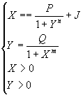
We transform the system to reduced variables X and Y that are equal to RAA and RBB.
P, Q and J equal RAEA/DA, RBEB/DB and RAZ/DA respectively. This transformation has two advantages. First, it reduces the number of parameters. Second, it makes the equations linear with respect to parameters (except for cooperativity indices). The natural phase space of this system is a rectangle
0 < X < P+J, 0 < Y < Q
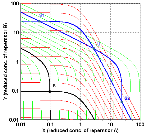
The solutions can be visualized on the graph. In Fig. 1 the black lines indicate the solutions for the first equation (for various P), the red lines – solutions of the second (for various Q). The cross points, where both equations are satisfied simultaneously, are stationary points.
Fig 1. The graphical solutions of system (III) at m=2, n=2 and J=0. For clarity, double-log scale is used. Red lines are plots of the first equation at various P, Green lines are plots of the second equation at variuos Q. To find the stationary points one should find the intersections of a red line and a green line. They may intersect in 1 stable point (black plot) or in 3 points (2 stable, 1 unstable, blue plot).
The analysis of the graphs immediately yields the following findings:
1. The curves start at finite value at one axis and end asymptotically parallel to the other.
2. The curves are smooth and monotonous
3. The number of cross points is odd.
It is easy to prove now, without any algebra, that either there is one stationary point that is stable, or three stationary points, the edge points are stable and the middle point is unstable. Such properties immediately hint for the presence of cusp catastrophe in the parameter space and pitchfork bifurcation in phase space.


