\Experimental Steps
From 2007.igem.org
(Difference between revisions)
(→Step 2: Characterize Amplifier) |
|||
| (14 intermediate revisions not shown) | |||
| Line 104: | Line 104: | ||
<!-- PLACE CONTENT IN HERE--> | <!-- PLACE CONTENT IN HERE--> | ||
| - | + | =Experiemental Steps= | |
| - | =Step 1: AHL Assay= | + | |
| + | ==Step 1: AHL Assay== | ||
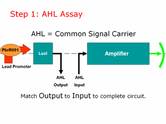
AHL is our common signal carrier between the two main components of our genetic circuit. The output coming from our lead promoter + LuxI is AHL. And the input going into the pLux part of our Amplifier is AHL. To make a working lead detector, the amount of AHL coming out of the first component must be sufficient to turn on the second component. Therefore, as in electrical engineering, we must measure and match our inputs and outputs to create a working genetic circuit. | AHL is our common signal carrier between the two main components of our genetic circuit. The output coming from our lead promoter + LuxI is AHL. And the input going into the pLux part of our Amplifier is AHL. To make a working lead detector, the amount of AHL coming out of the first component must be sufficient to turn on the second component. Therefore, as in electrical engineering, we must measure and match our inputs and outputs to create a working genetic circuit. | ||
| - | [[Image: | + | [[Image:step1lead.png|right]] |
| - | We used the well characterized part BBa_T9002 for our AHL assay. These cells take in AHL and give us a straight GFP output, without amplification or a positive feedback loop. We created a calibration curve and planned to use these cells to test the amount of AHL coming OUT of our lead promoter in response to different amounts of lead. We would then separately test the amplifier by adding known concentrations of AHL to determine how much AHL is necessary to give us a GFP output. Then we can put both pieces of information together to give us a lead sensor. | + | |
| + | |||
| + | We used the well characterized part BBa_T9002 for our AHL assay. These cells take in AHL and give us a straight GFP output, without amplification or a positive feedback loop. We created a calibration curve and planned to use these cells to test the amount of AHL coming OUT of our lead promoter in response to different amounts of lead. We would then separately test the amplifier by adding known concentrations of AHL to determine how much AHL is necessary to give us a GFP output. Then we can put both pieces of information together to give us a lead sensor.\ | ||
| + | |||
| + | |||
Registry Links: | Registry Links: | ||
| + | |||
[http://partsregistry.org/Part:BBa_T9002 BBa_T9002] | [http://partsregistry.org/Part:BBa_T9002 BBa_T9002] | ||
| + | |||
[http://partsregistry.org/Part:BBa_F2620 BBa_F2620] | [http://partsregistry.org/Part:BBa_F2620 BBa_F2620] | ||
| - | =Step 2: Characterize Amplifier= | + | ==Step 2: Characterize Amplifier== |
| - | + | ||
| - | + | ||
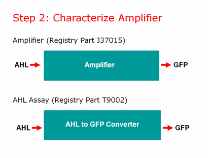
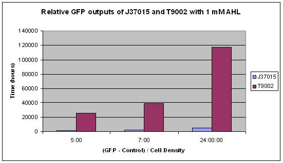
We characterized our amplifier and found some very unexpected results! | We characterized our amplifier and found some very unexpected results! | ||
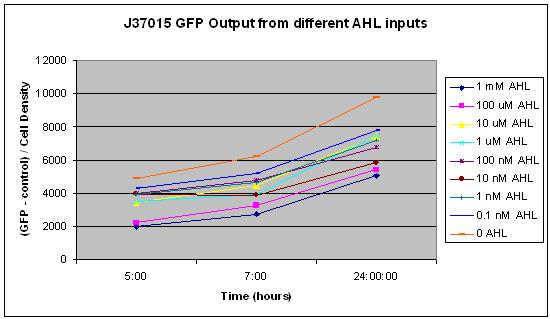
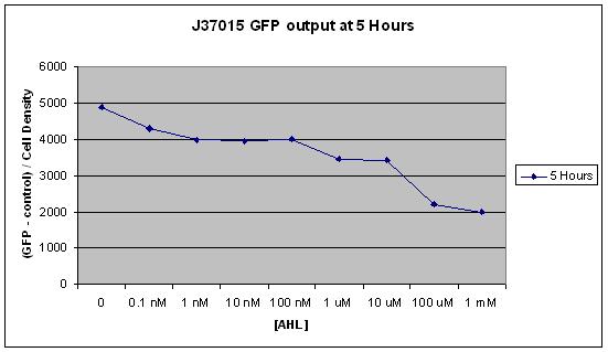
The main difference between J37015 and T9002 is that there is a positive feedback loop in J37015. So we would expect J37015 to make much more GFP than T9002 at the same AHL concentrations. However, J37015 actually made LESS GFP. | The main difference between J37015 and T9002 is that there is a positive feedback loop in J37015. So we would expect J37015 to make much more GFP than T9002 at the same AHL concentrations. However, J37015 actually made LESS GFP. | ||
| + | |||
| + | |||
| + | |||
| + | [[Image:step2lead.png|right]] | ||
| Line 127: | Line 137: | ||
Clearly, the amplifier did not work the way we had thought it would. This highlights the importance of part characterization. If synthetic biology is going to advance, parts in the registry must be well characterized to be useful for engineering purposes. We took it upon ourselves to characterize this part to ensure that others would not run into the same problems we did. | Clearly, the amplifier did not work the way we had thought it would. This highlights the importance of part characterization. If synthetic biology is going to advance, parts in the registry must be well characterized to be useful for engineering purposes. We took it upon ourselves to characterize this part to ensure that others would not run into the same problems we did. | ||
| + | ====Experiments==== | ||
| + | [http://partsregistry.org/Part:BBa_J37015:Experience The following information can also be found in the Registry.] | ||
| - | |||
| - | + | Part J37015 was tested by the Brown iGEM team in August 2007. Some interesting and very repeatable results were obtained. It was expected that this part, J37015, would produce significantly more GFP than the part T9002, which differs only in that it has no LuxI gene and therefore no positive feedback loop. It was also expected that higher amounts of AHL would cause J37015 to produce more GFP than low amounts of AHL. Both of these hypotheses were proven false. | |
| - | + | ||
| - | + | ||
| - | + | ||
| - | + | ||
| - | + | ||
| - | + | ||
| - | + | ||
| - | + | ||
| - | + | ||
| - | + | ||
| - | + | ||
| - | + | ||
| - | + | ||
| - | + | ||
In this experiment, 10 uL of a solution of AHL in water was mixed with 90 uL of LB and 3 uL of an overnight culture of cells. The concentrations 0, 0.1 nM, 1 nM, 10 nM, 100 nM, 1 uM, 10 uM, 100 uM, and 1 mM AHL were tested. These are the final concentrations of AHL in the solution with LB and cells, not the concentration of AHL in the water that was added to that solution. Measurements were made using a NanoDrop Spectrophotometer for Cell Density and a NanoDrop Flourospectrometer for GFP fluorescence at several time points over a 24 hour period. The average of all GFP measurements at the first measurement, time 0, was considered background fluorescence, and was subtracted from all subsequent GFP measurements. Additionally, all GFP measurements were divided by the cell density so that GFP per cell could be measured. This was to prevent noise from potential effects of AHL concentration on cell growth. | In this experiment, 10 uL of a solution of AHL in water was mixed with 90 uL of LB and 3 uL of an overnight culture of cells. The concentrations 0, 0.1 nM, 1 nM, 10 nM, 100 nM, 1 uM, 10 uM, 100 uM, and 1 mM AHL were tested. These are the final concentrations of AHL in the solution with LB and cells, not the concentration of AHL in the water that was added to that solution. Measurements were made using a NanoDrop Spectrophotometer for Cell Density and a NanoDrop Flourospectrometer for GFP fluorescence at several time points over a 24 hour period. The average of all GFP measurements at the first measurement, time 0, was considered background fluorescence, and was subtracted from all subsequent GFP measurements. Additionally, all GFP measurements were divided by the cell density so that GFP per cell could be measured. This was to prevent noise from potential effects of AHL concentration on cell growth. | ||
| Line 168: | Line 165: | ||
From these results, it appears that J37015 does seem to have some sort of function, though not as a signal amplification device. Further investigation will hopefully reveal the cause of these unexpected data. | From these results, it appears that J37015 does seem to have some sort of function, though not as a signal amplification device. Further investigation will hopefully reveal the cause of these unexpected data. | ||
| + | ==Step 3: Promoter and Lead Binding Protein== | ||
| + | [[Image:Step31.png|right|thumb|Lead Gene and Promoter in R. metallidurans]] | ||
| - | |||
| - | |||
| - | |||
| - | |||
| - | |||
| - | |||
| - | |||
| - | |||
| - | |||
| - | |||
| - | |||
| - | |||
| - | |||
Despite our amplifier results, we were not deterred. We still hoped to create a lead promoter and lead binding protein BioBrick to make our original simple lead detector. | Despite our amplifier results, we were not deterred. We still hoped to create a lead promoter and lead binding protein BioBrick to make our original simple lead detector. | ||
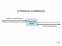
We obtained the genome of Ralstonia metallidurans. We then used PCR to pull out 15 different variations of the lead binding protein and lead gene. | We obtained the genome of Ralstonia metallidurans. We then used PCR to pull out 15 different variations of the lead binding protein and lead gene. | ||
| - | [[Image: | + | |
| + | [[Image:step32.png|right|thumb|Detailed look at promoter region.]] | ||
| + | |||
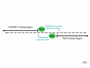
The diagram shows what the top and bottom strands of the genome where the lead binding protein, PbrR691 and the lead promoter (within this Non-Coding Region) lie. PbrA is a resistance gene that was not involved in our system but is relevant to the genome. | The diagram shows what the top and bottom strands of the genome where the lead binding protein, PbrR691 and the lead promoter (within this Non-Coding Region) lie. PbrA is a resistance gene that was not involved in our system but is relevant to the genome. | ||
| - | + | ||
| + | |||
According to the literature, the forward lead promoter is within this noncoding region. After communicating with the group that originally found this protein, we also suspected that a constitutive promoter region for PbrR691 could be found in the reverse direction in this noncoding region. Therefore, we used PCR and cloning to simply combine the PbrR691 coding region and blue noncoding region to GFP, hoping that we would not need to express PbrR691 under pTet’s constitutive control to get a responsive lead detector. | According to the literature, the forward lead promoter is within this noncoding region. After communicating with the group that originally found this protein, we also suspected that a constitutive promoter region for PbrR691 could be found in the reverse direction in this noncoding region. Therefore, we used PCR and cloning to simply combine the PbrR691 coding region and blue noncoding region to GFP, hoping that we would not need to express PbrR691 under pTet’s constitutive control to get a responsive lead detector. | ||
| Line 195: | Line 184: | ||
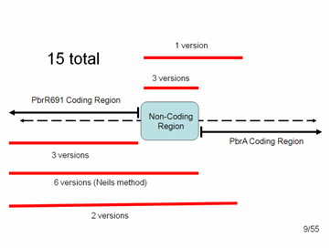
In the end we had 15 different variations of parts that we could add to the registry: | In the end we had 15 different variations of parts that we could add to the registry: | ||
| - | [[Image:step33.png]] | + | |
| + | [[Image:step33.png|right|thumb|PCR products of the promoter and gene.]] | ||
| + | |||
| + | |||
3 = just the Lead Binding Protein, PbrR691. | 3 = just the Lead Binding Protein, PbrR691. | ||
| + | |||
3 = just the Lead Promoter | 3 = just the Lead Promoter | ||
| + | |||
1 = the Lead Promoter + some small amount of PbrA with a stop codon. (We included about 100 bp of PbrA because we were afraid that pulling out the promoter alone might disrupt the distance between the protein start codon and the RBS within the non-coding region, which must be very specific for expression of the protein) | 1 = the Lead Promoter + some small amount of PbrA with a stop codon. (We included about 100 bp of PbrA because we were afraid that pulling out the promoter alone might disrupt the distance between the protein start codon and the RBS within the non-coding region, which must be very specific for expression of the protein) | ||
| + | |||
6 = Lead Binding Protein + Promoter (non-coding region), as per the method suggested to us by the original research group | 6 = Lead Binding Protein + Promoter (non-coding region), as per the method suggested to us by the original research group | ||
| + | |||
2 = Lead Binding Protein + Promoter + 100 bp of PbrA | 2 = Lead Binding Protein + Promoter + 100 bp of PbrA | ||
| - | == | + | ==Plans after PCR== |
| + | |||
| + | ====Planned Ligations==== | ||
| + | *All 15 parts into BioBrick plasmid | ||
| + | *pTet to PbrR691 alone | ||
| + | *All promoters and PbrR691 combinations to LuxI | ||
| + | *All promoters and PbrR691 combinations to GFP | ||
| + | *pTet-PbrR691 to promoters-LuxI | ||
| + | *pTet-PbrR691 to promoters-GFP | ||
| + | |||
| + | ====Completed Ligations==== | ||
| + | *All 15 parts into BioBrick plasmid | ||
| + | *All promoters and PbrR691 combinations to LuxI | ||
| + | *All promoters and PbrR691 combinations to GFP | ||
| - | |||
| - | |||
| - | |||
| - | |||
| - | |||
| - | |||
| - | |||
| - | |||
| - | |||
| - | |||
| - | |||
These ligations must be tested to see if the parts actually work. | These ligations must be tested to see if the parts actually work. | ||
| - | ==Our | + | ==Our Preliminary Results== |
| - | PbrR691/promoter combinations in presence of lead nitrate give no GFP production and no AHL production compared to control. Therefore, we decided to abandon | + | PbrR691/promoter combinations in presence of lead nitrate give no GFP production and no AHL production compared to control. Therefore, we decided to abandon the method of creating a lead detector using PbrR691/lead promoter. |
| - | + | ||
| - | + | ||
| - | + | ====Future Plans==== | |
| - | + | *Finish ligating Lead Binding Protein to pTet, where it can be constitutively expressed. | |
| + | *Finish ligating Lead promoter to GFP. | ||
| + | *Put both of the above components onto a single plasmid, transform E coli to generate a simple lead detector! | ||
Latest revision as of 02:29, 27 October 2007

