Synthesis of First Bacterial Computer
From 2007.igem.org
Wideloache (Talk | contribs) m |
|||
| (14 intermediate revisions not shown) | |||
| Line 2: | Line 2: | ||
There are three control experiments that our group has decided to conduct in conjunction with the construction of the bacterial computer. | There are three control experiments that our group has decided to conduct in conjunction with the construction of the bacterial computer. | ||
| - | The first experiment is to | + | The first experiment is to ensure that we can detect GFP and RFP at the same time in bacterial colonies |
Plac:RBS:RFP:RBS:GFP | Plac:RBS:RFP:RBS:GFP | ||
| Line 13: | Line 13: | ||
| - | The third deals with making sure that a polypeptide synthesized with different halves of the two different genes ( | + | The third deals with making sure that a polypeptide synthesized with different halves of the two different genes (because they are both fluorescent proteins) does not produce a positive phenotype. |
Plac:RBS:GFP1:hix:RFP2 | Plac:RBS:GFP1:hix:RFP2 | ||
| Line 19: | Line 19: | ||
Plac:RBS:RFP1:hix:GFP2 | Plac:RBS:RFP1:hix:GFP2 | ||
| - | In conjunction with these controls we will synthesize our first bacterial computer | + | In conjunction with these controls we will synthesize our first bacterial computer with the following starting orientation. |
T7 RFP1-hix-[GFP2-RFP1]-hix-[GFP2-TT]-hix-[RFP2-GFP1]-hix | T7 RFP1-hix-[GFP2-RFP1]-hix-[GFP2-TT]-hix-[RFP2-GFP1]-hix | ||
| Line 25: | Line 25: | ||
Note: The first half of each gene is ligated to an RBS | Note: The first half of each gene is ligated to an RBS | ||
| - | + | This construct represents the Davidson group's first HPP construct. (Shown to the right) [[Image:3N graph.jpg|thumb|"Node 1 = RFP; Node 2 = GFP; Node 3 = TT"]] <br> | |
| - | + | ||
| - | Note: We will lastly be testing the T7 promoter, and the UV5 hybrid pLac promoter. The second control experiment will also function as a second promoter tester and we plan on comparing results from the three promoter testers (Davidson’s PT, MW PT, and the newest PT) to discern which method of controlling gene expression we will use. | + | The solved orientation of nodes was decided upon by results from split-gene strength. Split RFP’s fluorescents is substantially less noticeable than GFP’s. We decided to ligate GFP after RFP in order to have a better chance of recognizing successfully-split RFP’s phenotype. |
| + | |||
| + | The starting orientation of the bacterial computer was decided upon by avoidance of “solved” phenotypes before flipping began. | ||
| + | |||
| + | Note: We will lastly be testing the T7 promoter, and the UV5 hybrid pLac promoter. The second control experiment will also function as a second promoter tester and we plan on comparing results from the three promoter testers (Davidson’s PT, MW PT, and the newest PT) to discern which method of controlling gene expression we will use. The ability to use split Cre protein as a node is still in testing as well. | ||
Latest revision as of 21:03, 23 July 2007
Now that we have an idea of which genes are “splittable” and therefore a number of nodes that we are able to work with, we can begin to build our first bacterial computer. There are three control experiments that our group has decided to conduct in conjunction with the construction of the bacterial computer.
The first experiment is to ensure that we can detect GFP and RFP at the same time in bacterial colonies
Plac:RBS:RFP:RBS:GFP
The second experiment is: if the problem is solved, will the construct show the desired phenotype.
T7:RBS:RFP1:hix:RFP2:RBS:GFP1:hix:GFP2
- A separate plasmid containing the gene for the T7 RNA polymerase will be co-transformed with the constructs that use the T7 RNA polymerase promoter. Plac:RBS:T7 RNAP gene
The third deals with making sure that a polypeptide synthesized with different halves of the two different genes (because they are both fluorescent proteins) does not produce a positive phenotype.
Plac:RBS:GFP1:hix:RFP2 and Plac:RBS:RFP1:hix:GFP2
In conjunction with these controls we will synthesize our first bacterial computer with the following starting orientation.
T7 RFP1-hix-[GFP2-RFP1]-hix-[GFP2-TT]-hix-[RFP2-GFP1]-hix
Note: The first half of each gene is ligated to an RBS
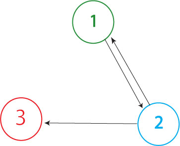
This construct represents the Davidson group's first HPP construct. (Shown to the right)
The solved orientation of nodes was decided upon by results from split-gene strength. Split RFP’s fluorescents is substantially less noticeable than GFP’s. We decided to ligate GFP after RFP in order to have a better chance of recognizing successfully-split RFP’s phenotype.
The starting orientation of the bacterial computer was decided upon by avoidance of “solved” phenotypes before flipping began.
Note: We will lastly be testing the T7 promoter, and the UV5 hybrid pLac promoter. The second control experiment will also function as a second promoter tester and we plan on comparing results from the three promoter testers (Davidson’s PT, MW PT, and the newest PT) to discern which method of controlling gene expression we will use. The ability to use split Cre protein as a node is still in testing as well.
