Tianjin/DIODE
From 2007.igem.org
Sunlovedie (Talk | contribs) |
Lovecarrot (Talk | contribs) (→Design) |
||
| (130 intermediate revisions not shown) | |||
| Line 3: | Line 3: | ||
|width="960px" style="padding: 10px; background-color: #0099FF" | | |width="960px" style="padding: 10px; background-color: #0099FF" | | ||
==Design== | ==Design== | ||
| - | [[Image: | + | |
| - | <br> | + | <font size="5" color="#60ff00">Brief Introduction of Bio-diode</font> |
| - | [[Image: | + | <br><br> |
| + | |||
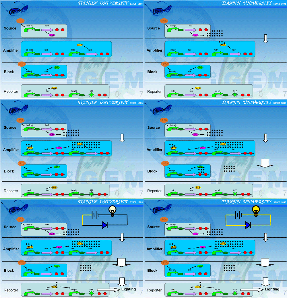
| + | <font size="3" color="#ffff00" rowspan=2 > The diode, one of the most significant parts in the electric integrate circuit and electronic equipment, functions as allowing the current get through when the diode is positive-biased, and cut off while it is negative-biased. When the negative voltage increases to a threshold, the diode tends to be negatively broken down. In this project, the molecular signal AHL is considered as the current of electric circuit.Three types of cells: [[Tianjin/DIODE/Generator cells|Generator cells]]、[[Tianjin/DIODE/Amplifier cells|Amplifier cells]] and [[Tianjin/DIODE/Block cells|Block cells]] are immobilized into small beads with a diameter of 0.5 millimeter. Then different beads are settled into particular parts of our specially designed equipment sequentially and respectively.The diode is built up with the amplifier cells and the block cells.The generator cells are thought as the electrical source and there are detector cells,which are considered as the lamp ,to detect the AHL. | ||
| + | |||
| + | <br>The liquid culture flows through the generator cells and carries the AHL signal into the amplifier cells which are activated to make more AHL signals. <br>Then the concentration of AHL accumulates to such a level that block cells could not eliminate them completely, and the rest could be detected by [[Tianjin/DIODE/Reporter cells|Detector cells]], a condition called ‘positive-biased pass’.</font><br> | ||
| + | |||
| + | |||
| + | |||
| + | <table width="99%" border="10" cellpadding="0" cellspacing="0" style="padding: 10px; background-color: #0099FF"> | ||
| + | <tr> | ||
| + | <td><center>[[Image:diodedh.gif|500px]] <font size="8" color="#0000CC">OK!</font> [[Image:happy.gif|150px]]</center></td> | ||
| + | </tr></table> | ||
| + | <br><br> | ||
| + | |||
| + | |||
| + | |||
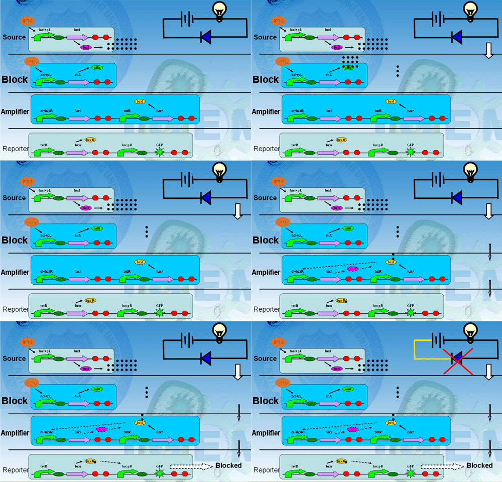
| + | <font size="3" color="#ffff00" rowspan=2 >On the contrary, if the positions of amplifier cells and block cells in our equipment are reversed, the AHL produced by generator cells would be degraded by block cells at the very beginning resulting in no amplification of the signal. Thus, hardly AHL could be detected in the outflow culture, a condition called ‘negative-biased block’. </font> | ||
| + | |||
| + | |||
| + | <table width="99%" border="10" cellpadding="0" cellspacing="0" style="padding: 10px; background-color: #0099FF"> | ||
| + | <tr> | ||
| + | <td><center>[[Image:diodeblock.gif|500px]] <font size="8" color="#0000CC">Blocked!</font>[[Image:sad.gif]]</center></td> | ||
| + | </tr></table> | ||
| + | <br><br> | ||
| + | |||
| + | |||
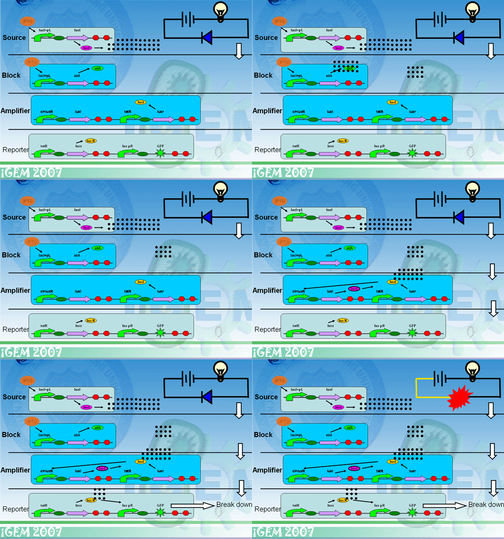
| + | <font size="3" color="#ffff00" rowspan=2 >When the input AHL signal produced by the generator cells is stronger than digesting capacity of the block cells , the amplifier cells will still be activated by the left AHL signal, which is what we called "breakdown".</font> | ||
| + | <table width="99%" border="10" cellpadding="0" cellspacing="0" style="padding: 10px; background-color: #0099FF"> | ||
| + | <tr> | ||
| + | <td><center>[[Image:breakdown.gif|500px]] <font size="5" color="#0000CC">Broken down!</font>[[Image:cry.gif]]</center></td> | ||
| + | </tr></table> | ||
| + | <br><br> | ||
|- | |- | ||
|width="960px" style="padding: 10px; background-color: #00FFFF" | | |width="960px" style="padding: 10px; background-color: #00FFFF" | | ||
| - | |||
| - | + | ==Model== | |
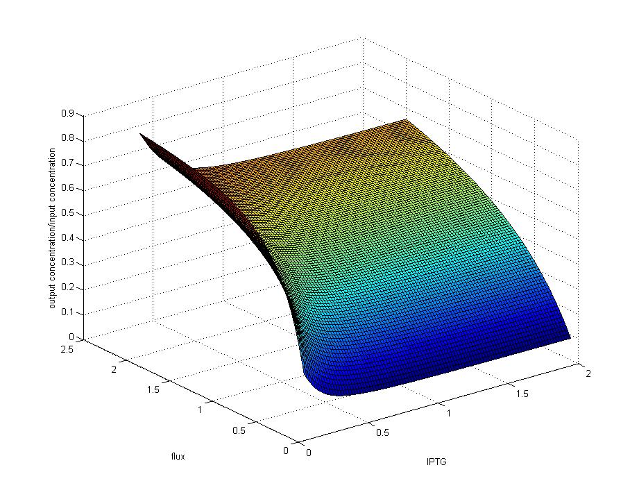
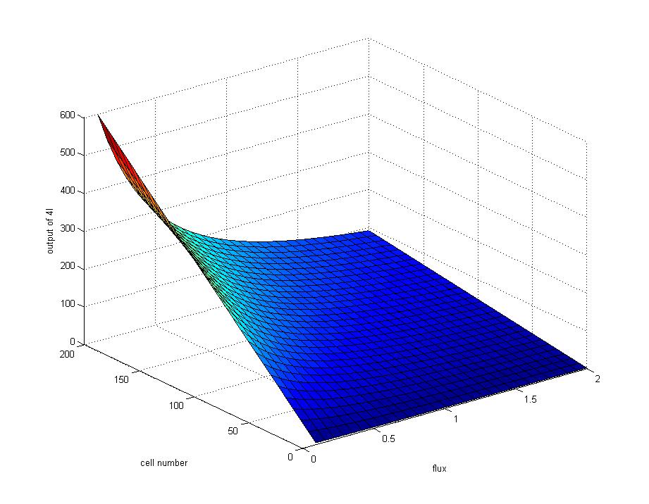
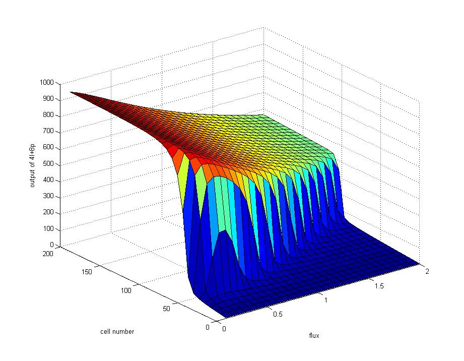
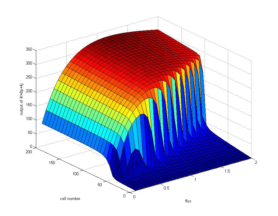
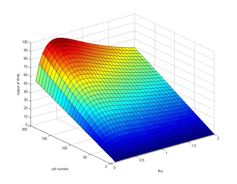
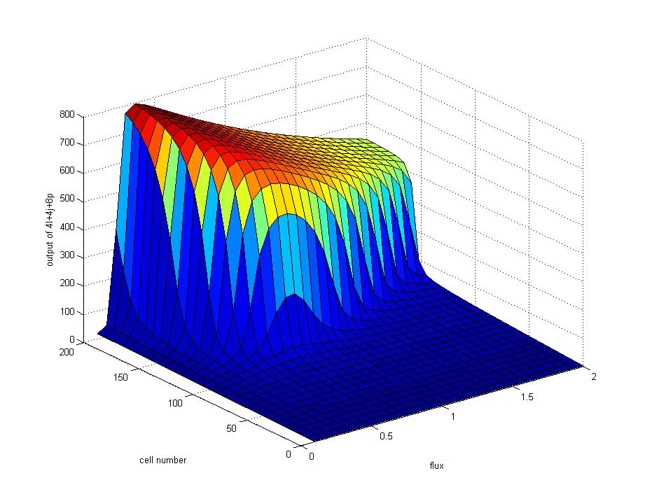
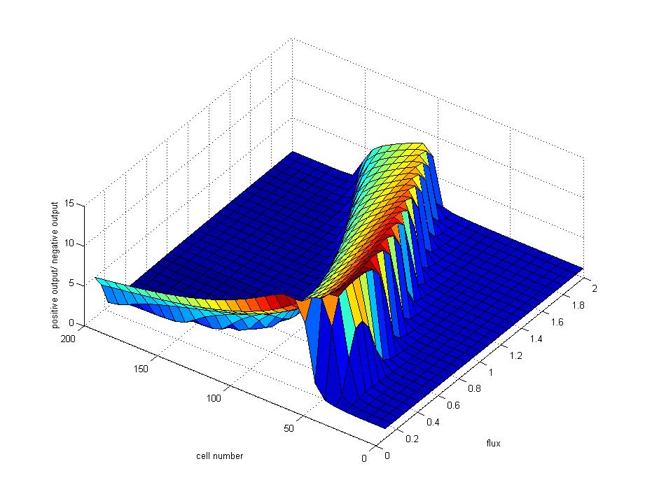
| - | + | We construct a mathematical model to simulate the features of our bio-diode mainly by Ordinary Differential Equations. With the help of this model,we show the ideal performance of each immobilized cells ,especially the amplifier cells, under different cell densities and flux rates.We also examine the features of different cells under the conditions of positive-biased through, negative-biased block and negative-biased breakdown. Thus the data and conclusion derived from the model are quite helpful for our further wet experiment. | |
| - | + | <br> | |
| - | [[ | + | <font size="3" color="#0000CC" bgcolor="#FF9933">1. </font>[[Tianjin/DIODE/Model0|<font size="3" color="#0000CC">Model design and construction</font>]] |
| - | + | ||
| - | + | ||
| - | + | ||
| - | + | <font size="3" color="#0000CC">2. <font size="3" color="#0000CC">Model result</font> | |
| - | + | ||
| - | == | + | <font size="3" color="#0000CC">2.1 </font>[[Tianjin/DIODE/Model|<font size="3" color="#0000CC">Model of Generator Cells</font>]]<br>[[Image:TJU4L1.jpg|80px]][[Image:TJU4L2.jpg|80px]][[Image:TJU4L.jpg|80px]][[Image:TJU8P1.jpg|80px]][[Image:TJU8P2.jpg|80px]] |
| - | + | ||
| - | + | ||
<br> | <br> | ||
| + | <font size="3" color="#0000CC">2.2 </font>[[Tianjin/DIODE/Model1|<font size="3" color="#0000CC">Model of Block Cells</font>]] | ||
| + | <br>[[Image:TJU4j.jpg|80px]][[Image:TJU4j2.jpg|80px]] | ||
<br> | <br> | ||
| - | <font size=" | + | <font size="3" color="#0000CC">2.3 </font>[[Tianjin/DIODE/Model2|<font size="3" color="#0000CC">Model of Amplifier Cells</font>]] |
| - | + | <br>[[Image:TJU8P1.jpg|80px]][[Image:TJU8P2.jpg|80px]] | |
| - | < | + | |
| - | + | ||
| - | + | ||
<br> | <br> | ||
| + | <font size="3" color="#0000CC">2.4 </font>[[Tianjin/DIODE/Model3|<font size="3" color="#0000CC">Model of whole system</font>]] | ||
| + | <br>[[Image:TJUI.jpg|80px]][[Image:TJUI1.jpg|80px]][[Image:TJUI2.jpg|80px]][[Image:TJUIJ.jpg|80px]][[Image:TJUIJP.jpg|80px]][[Image:TJUzf.jpg|80px]] | ||
<br> | <br> | ||
| - | + | |- | |
| - | + | |width="960px" style="padding: 10px; background-color: #0099FF" | | |
| - | + | ||
| - | + | ==Experiment== | |
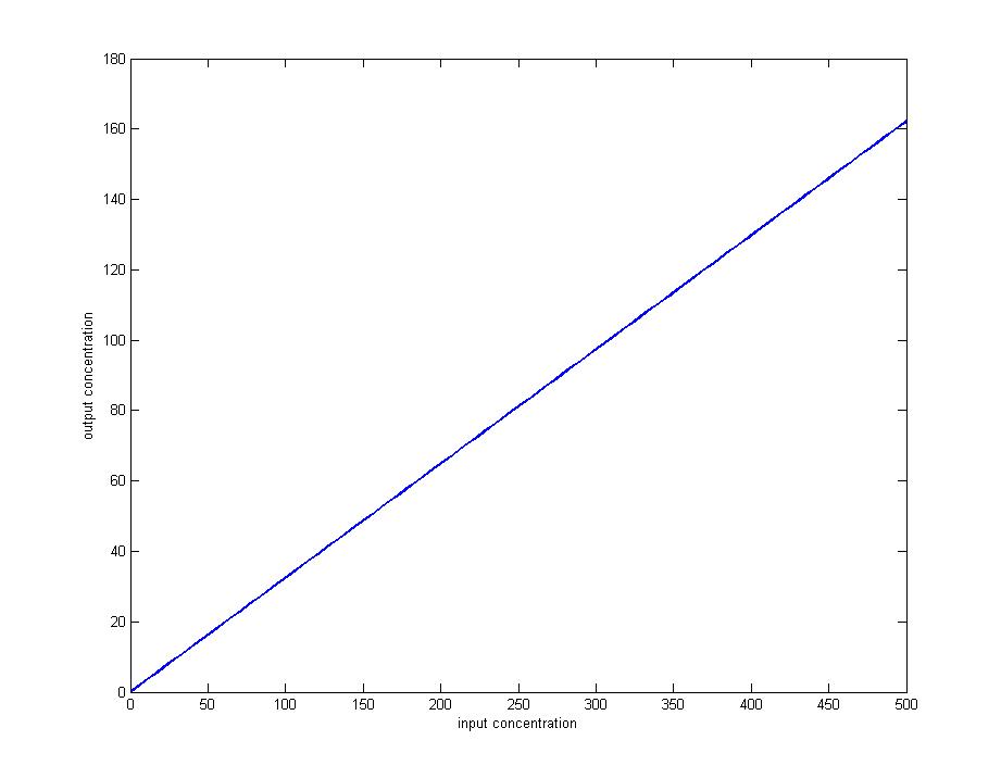
| - | + | The function of detector cells has to be defined first to build a relationship between the concentration of AHL and the fluorescence intensity. The experimental results show that at a range of AHL concentrations the concentration of AHL is proportional to the fluorescence intensity, so within this extent, the fluorescence intensity could be regarded as the value of output signal which is convenient to detect and quantificationally defined. Then we test the functions of other three types of cells in immobilized beads by using the detector cells, proving that the generator and block cells work perfectly but the amplified cells should be improved due to the self-induction of its Lux Promoter. Finally, the three types of cells are fulfilled into our particular designed equipment whose functions are also researched carefully, and in order to solve the problem of amplifier cells, we transfer this part into another plasmid whose replication is controlled by IPTG. Although the data are not the same as our in silico model, it is substantiated that every part of our design has worked well and the main characters of diode including the 'positive-biased through', 'negative-biased block', 'negative-biased breakdown' are realized by our equipment. | |
| - | + | ||
| - | + | <font size="3" color="#0000CC">1.</font>[[Tianjin/DIODE/Experiment|<font size="3" color="#0000CC">Data and Graphs of Detector cells</font>]] | |
| - | + | ||
| - | < | + | |
<br> | <br> | ||
<br> | <br> | ||
| - | <font size=" | + | <font size="3" color="#0000CC">2.</font>[[Tianjin/DIODE/Experiment1|<font size="3" color="#0000CC">Function of immobilized cells</font>]] |
| - | + | <br> | |
| - | < | + | <br> |
| + | <font size="3" color="#0000CC">3.</font>[[Tianjin/DIODE/Experiment2|<font size="3" color="#0000CC">Assembly of equipment</font>]] | ||
<br> | <br> | ||
<br> | <br> | ||
| - | |||
| - | |||
| - | |||
| - | |||
| - | |||
| - | |||
| - | |||
| - | |||
| - | |||
| - | |||
Latest revision as of 03:52, 27 October 2007
DesignBrief Introduction of Bio-diode
The diode, one of the most significant parts in the electric integrate circuit and electronic equipment, functions as allowing the current get through when the diode is positive-biased, and cut off while it is negative-biased. When the negative voltage increases to a threshold, the diode tends to be negatively broken down. In this project, the molecular signal AHL is considered as the current of electric circuit.Three types of cells: Generator cells、Amplifier cells and Block cells are immobilized into small beads with a diameter of 0.5 millimeter. Then different beads are settled into particular parts of our specially designed equipment sequentially and respectively.The diode is built up with the amplifier cells and the block cells.The generator cells are thought as the electrical source and there are detector cells,which are considered as the lamp ,to detect the AHL.
On the contrary, if the positions of amplifier cells and block cells in our equipment are reversed, the AHL produced by generator cells would be degraded by block cells at the very beginning resulting in no amplification of the signal. Thus, hardly AHL could be detected in the outflow culture, a condition called ‘negative-biased block’.
| |||
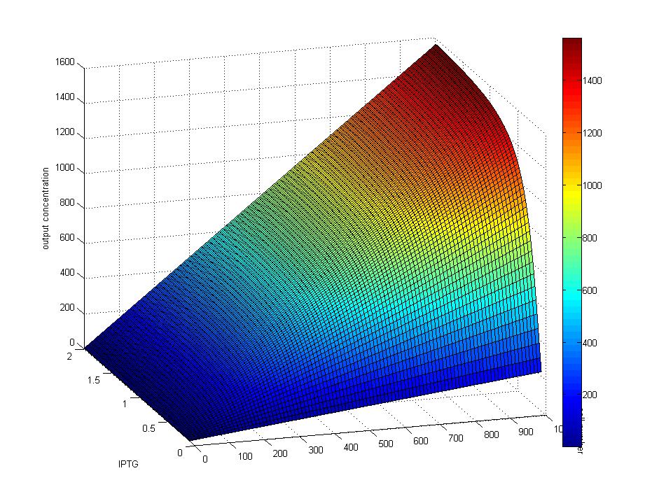
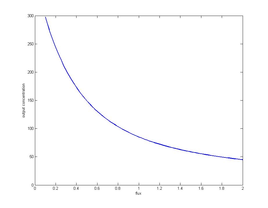
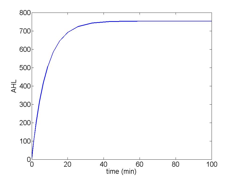
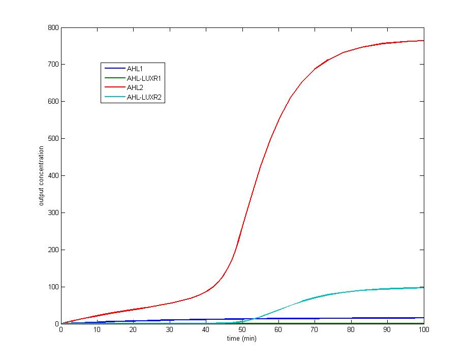
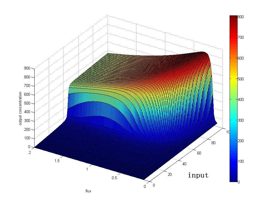
ModelWe construct a mathematical model to simulate the features of our bio-diode mainly by Ordinary Differential Equations. With the help of this model,we show the ideal performance of each immobilized cells ,especially the amplifier cells, under different cell densities and flux rates.We also examine the features of different cells under the conditions of positive-biased through, negative-biased block and negative-biased breakdown. Thus the data and conclusion derived from the model are quite helpful for our further wet experiment.
2. Model result 2.1 Model of Generator Cells | |||
ExperimentThe function of detector cells has to be defined first to build a relationship between the concentration of AHL and the fluorescence intensity. The experimental results show that at a range of AHL concentrations the concentration of AHL is proportional to the fluorescence intensity, so within this extent, the fluorescence intensity could be regarded as the value of output signal which is convenient to detect and quantificationally defined. Then we test the functions of other three types of cells in immobilized beads by using the detector cells, proving that the generator and block cells work perfectly but the amplified cells should be improved due to the self-induction of its Lux Promoter. Finally, the three types of cells are fulfilled into our particular designed equipment whose functions are also researched carefully, and in order to solve the problem of amplifier cells, we transfer this part into another plasmid whose replication is controlled by IPTG. Although the data are not the same as our in silico model, it is substantiated that every part of our design has worked well and the main characters of diode including the 'positive-biased through', 'negative-biased block', 'negative-biased breakdown' are realized by our equipment. 1.Data and Graphs of Detector cells
|
