Waterloo
From 2007.igem.org
| (192 intermediate revisions not shown) | |||
| Line 1: | Line 1: | ||
| - | <center | + | <center> [[Image:UW_iGEMLogoHeader.png | 935px]] </center> |
| + | <br> | ||
| - | == Our Team = | + | {| style="border-spacing:0px; border-width:thin; border-color:black; border-style:solid" |
| - | The UW iGEM team is a very interdisciplinary group. Our team members span | + | |- |
| + | | style="font-size:x-large; font-weight:bold; border-bottom-width:thin; border-bottom-color:black; border-bottom-style:solid; font-size:x-large; font-weight:bold; padding:5px; background-color:#FBCC30" | Our Team | ||
| + | |- | ||
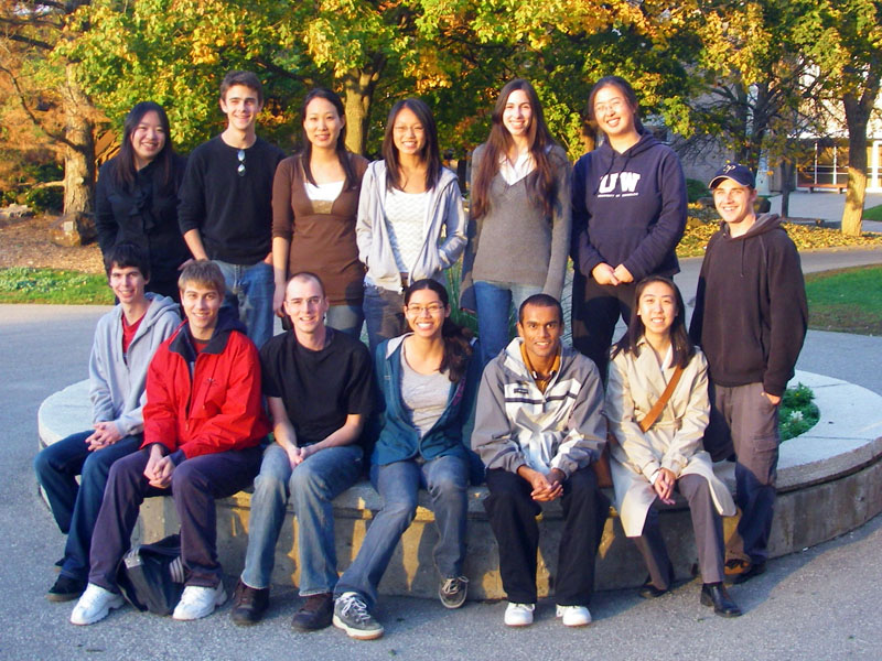
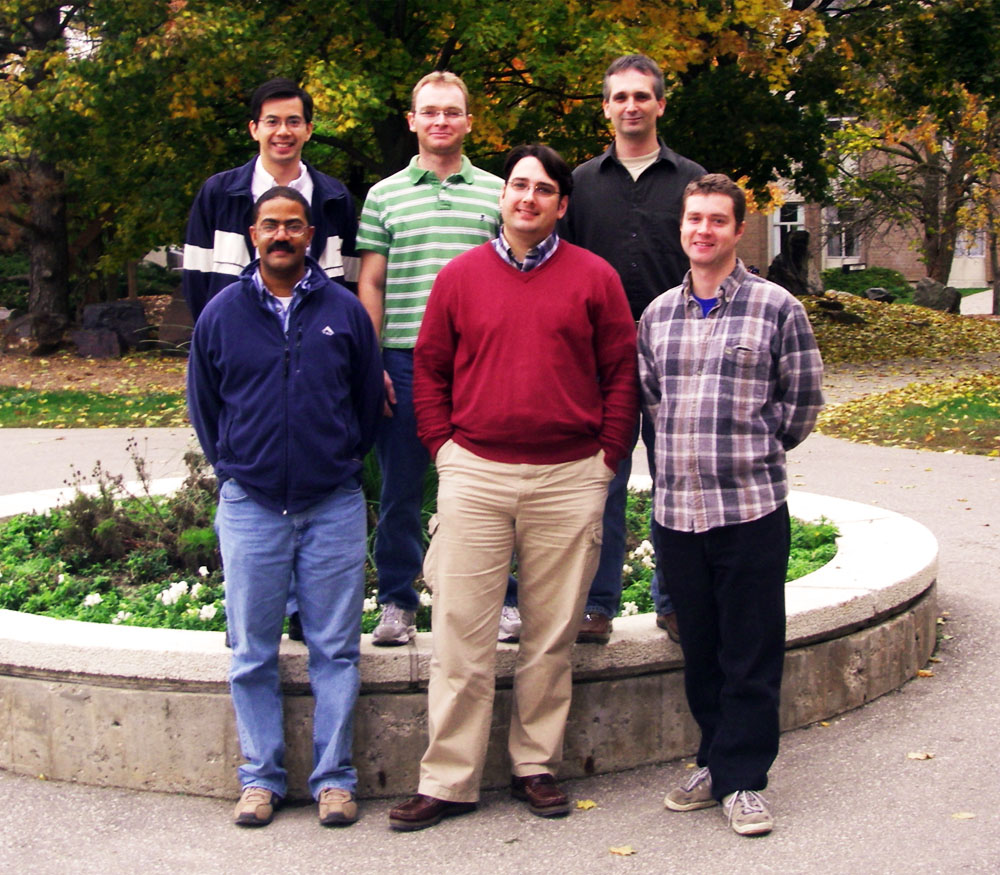
| + | | style="padding:5px" | [[Image:Group photo mimi1.JPG|470px|left|thumb|Undergraduate Members]] [[Image:UW_Advisors.jpg|407px|center|thumb|Faculty and Graduate Advisors]] | ||
| + | |- | ||
| + | | style="padding:5px" | The UW iGEM team is a very interdisciplinary group. Our team members span three faculties: Science, Mathematics, and Engineering, and represent a wide range of undergraduate programs: Biology, Biomedical Sciences, Biochemistry, Computer Science, Bioinformatics, Computer Engineering, Electrical Engineering, Chemical Engineering, Systems Design Engineering, and Mathematical Physics. | ||
| - | + | Drawing on our diverse backgrounds, we bring a wide range of skills and modes of creative thinking to our iGEM project. The iGEM competition is providing us with an opportunity to become more familiar with the emerging field of synthetic biology in an engaging and fun atmosphere. In addition to gaining experience in the design, construction, and analysis of genetic circuits, we are also meeting the challenge of bringing together a large, diverse group toward a common goal. | |
| - | + | ||
| - | + | ||
| - | + | ||
| - | + | ||
| - | + | |} | |
| - | + | ||
| - | + | ||
| - | + | ||
| - | = | + | <br clear="all"> |
| - | + | ||
| - | + | ||
| - | == | + | {| style="border-spacing:0px; border-width:thin; border-color:black; border-style:solid; width:100%" |
| - | + | |- | |
| + | | colspan="4" style="border-bottom-width:thin; border-bottom-color:black; border-bottom-style:solid; font-size:x-large; font-weight:bold; padding:5px; background-color:#FBCC30" | Our Project | ||
| + | |- | ||
| + | | colspan="4" style="padding:5px; font-size:large" | Abstract | ||
| + | |- | ||
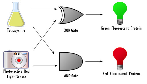
| + | | colspan="2" style="vertical-align:top; border-bottom-width:thin; border-bottom-color:black; border-bottom-style:solid; padding:5px" | The goal of this project is to design a basic device for computing. Our idea was to reproduce a circuit element called a half adder with DNA, which takes in two 1-bit inputs, adds them, and outputs a sum and a carry. Our device responds to two inputs: red light and the chemical tetracycline. The input sensors control a set of genetic switches in order to carry out the computation and fluoresces green, red, or neither, depending on the outcome. | ||
| - | + | Half adders are used as building blocks for full adders, which perform calculations similar to long addition but in binary. They are also an essential component in a device called the Arithmetic Logic Unit (ALU), a fundamental building block for the central processing unit in a modern computer. ALUs perform simple and complex operations such as bitwise logical operations and mathematical operations. | |
| + | The constructs for the half adder were built in parallel as well as the testing constructs. A future extension to this project would be to create a full adder. More information on each stage of the project is available below. | ||
| + | | colspan="2" style="border-bottom-width:thin; border-bottom-color:black; border-bottom-style:solid; padding:5px; vertical-align:middle" | [[Image:Design schematic.jpg|thumb|center|475px|Schematic Design of the Biological Half-Adder]] | ||
| + | |- | ||
| + | | style="width:25%; border-right-width:thin; border-right-color:black; border-right-style:solid; font-size:large; text-align:left; padding:5px; background-color:#FBCC30" | [[Project | Project Design]] || style="width:25%; border-right-width:thin; border-right-color:black; border-right-style:solid; font-size:large; text-align:left; padding:5px; background-color:#FBCC30" | [[Modelling | Mathematical Modelling]] || style="width:25%; border-right-width:thin; border-right-color:black; border-right-style:solid; font-size:large; text-align:left; padding:5px; background-color:#FBCC30" | [[Construction_and_Testing | Construction and Testing]] || style="width:25%; font-size:large; text-align:left; padding:5px; background-color:#FBCC30" | [[Future_Work | Future Work]] | ||
| + | |- | ||
| + | | style="vertical-align:top; border-right-width:thin; border-right-color:black; border-right-style:solid; padding:5px" | | ||
| + | * Binary addition and boolean logic | ||
| + | * Half-adder vs. full-adder designs | ||
| + | * Biological half-adder implementation | ||
| + | | style="vertical-align:top; border-right-width:thin; border-right-color:black; border-right-style:solid; padding:5px" | | ||
| + | * Modelling the gene regulatory network | ||
| + | * Simulation results | ||
| + | | style="vertical-align:top; border-right-width:thin; border-right-color:black; border-right-style:solid; padding:5px" | | ||
| + | * Strategy for half-adder construction | ||
| + | * Testing constructs for device | ||
| + | * Test execution plan | ||
| + | * Submitted parts | ||
| + | | style="vertical-align:top; padding:5px" | | ||
| + | * Explanation of a full adder | ||
| + | * Gene design for full adder | ||
| + | * Implementation plan | ||
| + | |} | ||
| + | <br clear="all"> | ||
| + | {| style="border-spacing:0px; border-width:thin; border-color:black; border-style:solid; width:100%; text-align:center" | ||
| + | |- | ||
| + | | style="font-size:x-large; font-weight:bold; font-size:x-large; font-weight:bold; padding:5px; background-color:#FBCC30; border-bottom-width:thin; border-bottom-color:black; border-bottom-style:solid; text-align:left" colspan="15" | Acknowledgements | ||
| + | |- | ||
| + | | colspan="3" | [[Image:Fsf_logo.gif|150px]] || colspan="3" | [[Image:MEF_logo.gif|150px]] || colspan="3" | [[Image:SFF_Logo.gif|150px]] || colspan="3" | [[Image:WEEFLogo.jpg|150px]] || colspan="3" | [[Image:WatSEF_Logo.jpg|150px]] | ||
| + | |- | ||
| + | | colspan="3" | [http://www.science.uwaterloo.ca/fsf/index.html Faculty of Science Foundation ] || colspan="3" | [http://www.student.math.uwaterloo.ca/~mefcom/ Mathematics Endowment Fund ] || colspan="3" | [http://www.eng.uwaterloo.ca/~sff/ Sir Sanford Fleming Foundation] || colspan="3" | [http://www.weef.uwaterloo.ca/ Waterloo Engineering Endowment Fund] || colspan="3" | [http://www.science.uwaterloo.ca/~watsef/mainpage.html Waterloo Science Endowment Fund] | ||
| + | |- | ||
| + | | colspan="15" | | ||
| + | |- | ||
| + | | colspan="5" | [[Image:UW_EngFacLogo.PNG |150px]] || colspan="5" | [[Image:UW_SciFacLogo.PNG|150px]] || colspan="5" | [[Image:UW_MathFacLogo.PNG|150px]] | ||
| + | |- | ||
| + | | colspan="5" | [http://www.engineering.uwaterloo.ca University of Waterloo Faculty of Engineering] || colspan="5" | [http://www.science.uwaterloo.ca University of Waterloo Faculty of Science] || colspan="5" | [http://www.math.uwaterloo.ca University of Waterloo Faculty of Mathematics] | ||
| + | |- | ||
| + | | colspan="15" | | ||
| + | |- | ||
| + | | colspan="5" style="padding:5px" | [[Image:UW_Waterloocrest.PNG | 150px]] || colspan="10" style="text-align:left; padding:5px" | We would like to thank the following people for their support and guidance: | ||
| + | * Dr. Trevor Charles | ||
| + | * Dr. Barbara Moffatt | ||
| + | * Dr. Joshua Neufeld | ||
| + | |} | ||
| - | = | + | <br clear="all"> |
| - | + | <center> | |
| - | + | [[Waterloo | Home ]] | [[Project | Project]] | [[Modelling | Mathematical Modelling]] | [[Construction_and_Testing | Construction and Testing]] | [[Future_Work | Future Work]] | |
| - | + | </center> | |
| - | + | ||
| - | + | ||
| - | [[ | + | |
| - | + | ||
| - | + | ||
| - | + | ||
| - | + | ||
| - | + | ||
| - | + | ||
| - | [[ | + | |
| - | + | ||
| - | + | ||
| - | + | ||
| - | [[ | + | |
| - | + | ||
| - | + | ||
| - | + | ||
| - | [[ | + | |
| - | + | ||
| - | + | ||
| - | + | ||
| - | + | ||
| - | + | ||
| - | + | ||
| - | + | ||
| - | + | ||
| - | + | ||
| - | + | ||
| - | + | ||
| - | + | ||
| - | + | ||
| - | + | ||
| - | + | ||
| - | + | ||
| - | + | ||
| - | + | ||
| - | + | ||
| - | + | ||
| - | + | ||
| - | + | ||
| - | + | ||
| - | + | ||
| - | + | ||
| - | + | ||
| - | + | ||
| - | + | ||
| - | + | ||
| - | + | ||
| - | + | ||
| - | + | ||
| - | + | ||
| - | + | ||
| - | + | ||
| - | + | ||
| - | [ | + | |
| - | + | ||
| - | + | ||
Latest revision as of 04:02, 27 October 2007

| Our Team |
| The UW iGEM team is a very interdisciplinary group. Our team members span three faculties: Science, Mathematics, and Engineering, and represent a wide range of undergraduate programs: Biology, Biomedical Sciences, Biochemistry, Computer Science, Bioinformatics, Computer Engineering, Electrical Engineering, Chemical Engineering, Systems Design Engineering, and Mathematical Physics.
Drawing on our diverse backgrounds, we bring a wide range of skills and modes of creative thinking to our iGEM project. The iGEM competition is providing us with an opportunity to become more familiar with the emerging field of synthetic biology in an engaging and fun atmosphere. In addition to gaining experience in the design, construction, and analysis of genetic circuits, we are also meeting the challenge of bringing together a large, diverse group toward a common goal. |
| Our Project | |||
| Abstract | |||
| The goal of this project is to design a basic device for computing. Our idea was to reproduce a circuit element called a half adder with DNA, which takes in two 1-bit inputs, adds them, and outputs a sum and a carry. Our device responds to two inputs: red light and the chemical tetracycline. The input sensors control a set of genetic switches in order to carry out the computation and fluoresces green, red, or neither, depending on the outcome.
Half adders are used as building blocks for full adders, which perform calculations similar to long addition but in binary. They are also an essential component in a device called the Arithmetic Logic Unit (ALU), a fundamental building block for the central processing unit in a modern computer. ALUs perform simple and complex operations such as bitwise logical operations and mathematical operations. The constructs for the half adder were built in parallel as well as the testing constructs. A future extension to this project would be to create a full adder. More information on each stage of the project is available below. | |||
| Project Design | Mathematical Modelling | Construction and Testing | Future Work |
|
|
|
|
Home | Project | Mathematical Modelling | Construction and Testing | Future Work
