Tianjin/DIODE/Model3
From 2007.igem.org
Lovecarrot (Talk | contribs) |
Lovecarrot (Talk | contribs) |
||
| (6 intermediate revisions not shown) | |||
| Line 1: | Line 1: | ||
| - | Figure 1: The positive-biased condition of biodiode. Cell number in all three picture refer to the cell density of generator cells (4L). The middle graph indicates the concentration of AHL rises quickly to a high level after the amplifier cells are activated by the enviromental AHL signal (input signal). The biodiode could reach to the condition of positive-biased under a high cell density of 4L or a slow flux rate.(right graph) | + | Figure 1: The positive-biased condition of biodiode. <br> |
| - | [[Image:TJUI.jpg|300px]] | + | Cell number in all three picture refer to the cell density of generator cells (4L). The middle graph indicates the concentration of AHL rises quickly to a high level after the amplifier cells are activated by the enviromental AHL signal (input signal). The biodiode could reach to the condition of positive-biased under a high cell density of 4L or a slow flux rate.(right graph) |
| + | <br> | ||
| + | [[Image:TJUI.jpg|300px]][[Image:TJUI1.jpg|300px]][[Image:TJUI2.jpg|300px]] | ||
| + | |||
| + | Figure 2: The negative-biased condition of biodiode.<br> | ||
| + | The output AHL concentration maintains at a low level unless the density of generator cells reaches to a very high level. Under the latter condition, the amounts of produced AHL signal are so large that AHL left after passing through the block cells could still reaches to the threshold of activating the amplified cells, a condition called 'break down' | ||
| + | <br>[[Image:TJUI.jpg|300px]] [[Image:TJUIJ.jpg|300px]][[Image:TJUIJP.jpg|300px]] | ||
| + | |||
| + | Figure 3: In order to keep the biodiode work stably and avoid the appearance of break-down, both the flux rate and density of generator cells should be considered seriously. The ratio of positive output to negative input is employed to represent the quality of a biodiode. Since a ideal diodiode should have a maximum positive output and a minimum negative input, the ridge of the graph figure out the optimum condition for the work of biodiode.<br> | ||
| + | [[Image:TJUzf.jpg|300px]] | ||
Latest revision as of 15:07, 26 October 2007
Figure 1: The positive-biased condition of biodiode.
Cell number in all three picture refer to the cell density of generator cells (4L). The middle graph indicates the concentration of AHL rises quickly to a high level after the amplifier cells are activated by the enviromental AHL signal (input signal). The biodiode could reach to the condition of positive-biased under a high cell density of 4L or a slow flux rate.(right graph)
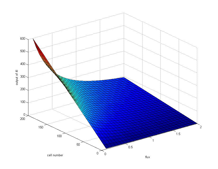
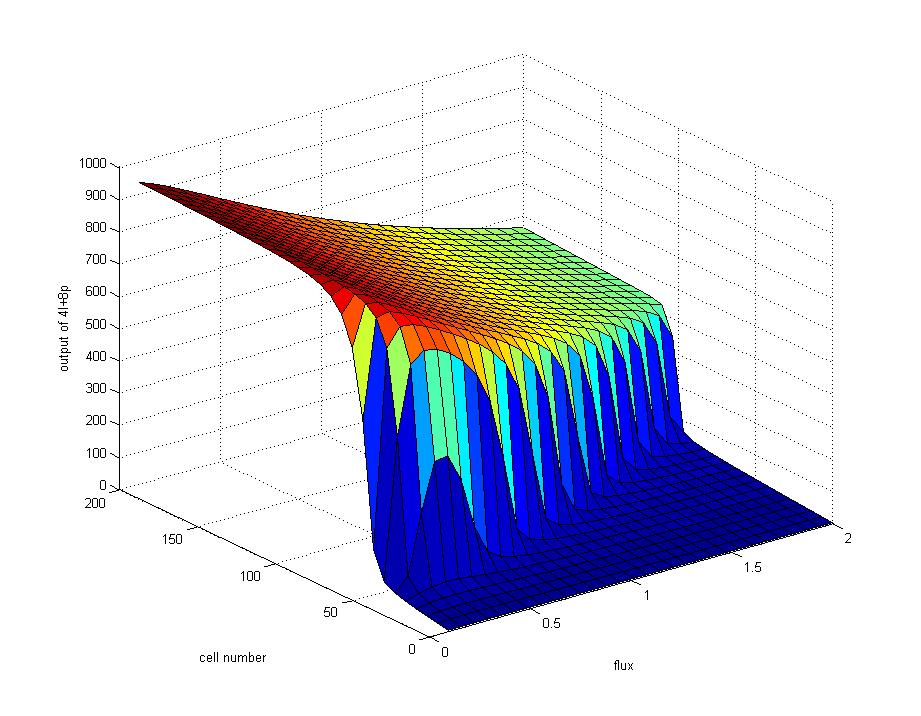
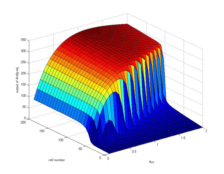
Figure 2: The negative-biased condition of biodiode.
The output AHL concentration maintains at a low level unless the density of generator cells reaches to a very high level. Under the latter condition, the amounts of produced AHL signal are so large that AHL left after passing through the block cells could still reaches to the threshold of activating the amplified cells, a condition called 'break down'

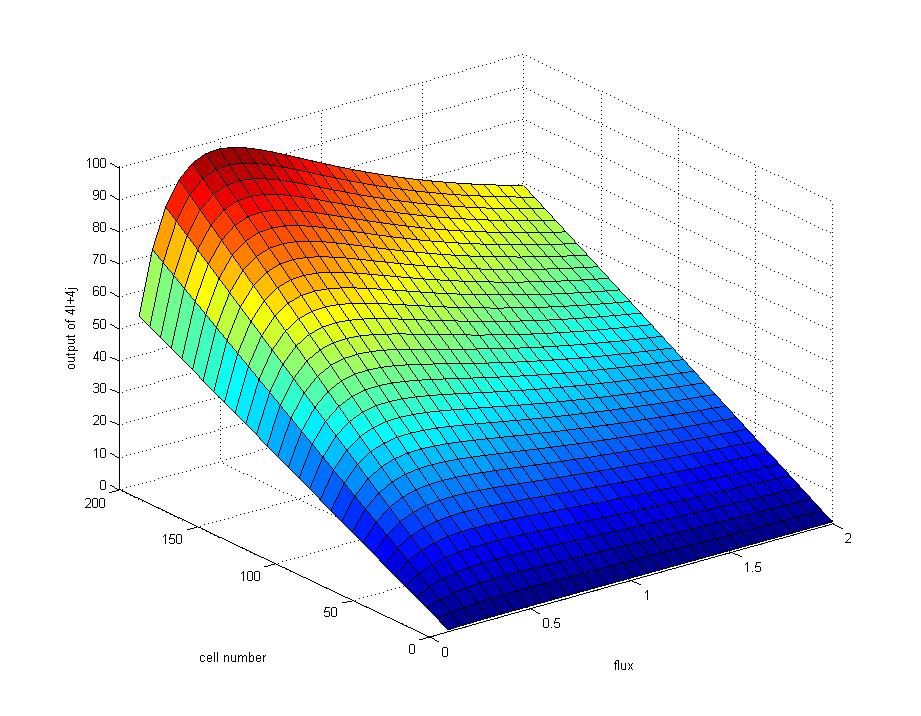
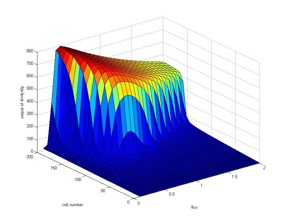
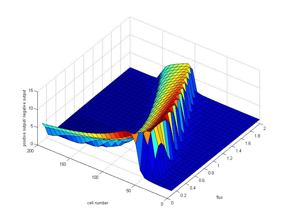
Figure 3: In order to keep the biodiode work stably and avoid the appearance of break-down, both the flux rate and density of generator cells should be considered seriously. The ratio of positive output to negative input is employed to represent the quality of a biodiode. Since a ideal diodiode should have a maximum positive output and a minimum negative input, the ridge of the graph figure out the optimum condition for the work of biodiode.
