Tianjin/FLIP-FLOP
From 2007.igem.org
Lovecarrot (Talk | contribs) (→<font size="4" color="#0000CC">Experiment</font>) |
|||
| (22 intermediate revisions not shown) | |||
| Line 3: | Line 3: | ||
|width="960px" style="padding: 10px; background-color: #FFFF99" | | |width="960px" style="padding: 10px; background-color: #FFFF99" | | ||
==<font size="4" color="#0000CC">Design</font>== | ==<font size="4" color="#0000CC">Design</font>== | ||
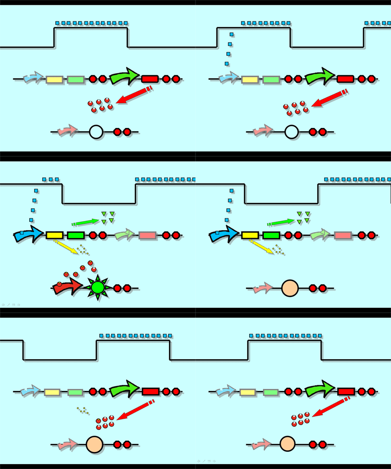
| - | Flip-Flop, a huge family of basic electric elements, is widely applied to the field of electric circuit and construction of database. One of the most common members of this family is RS Flip-Flop, the key part of which is a clock-controlled element. Based on the conception of "Flip- | + | Flip-Flop, a huge family of basic electric elements, is widely applied to the field of electric circuit and construction of database. One of the most common members of this family is RS Flip-Flop, the key part of which is a clock-controlled element. Based on the the “Latch and Enable Control" conception of "Flip-Flop" and synthetic biology, we designed the Genetical RS Flip-Flop whose output signal (Green Fluorescence protein) is regulated by input signal (the addition of IPTG). Besides, we modulate the performance of Genetical RS FLIP-FLOP to optimize our original design. |
| - | <font size="3" color="#0099CC">'''1.'''</font><font size="3" color="#0099CC">'''Introduction to the | + | <font size="3" color="#0099CC">'''1.'''</font><font size="3" color="#0099CC">'''Introduction to the Logic Rules of Our Flip-Flop''' |
</font> | </font> | ||
<br><br> | <br><br> | ||
| - | <table width=" | + | <table width="89%" border="10" cellpadding="0" cellspacing="20" style="padding: 10px; background-color: #FFFF99"> |
<tr> | <tr> | ||
<td><center>[[Image:TJUzmlrules.jpg]]</center></td> | <td><center>[[Image:TJUzmlrules.jpg]]</center></td> | ||
| Line 15: | Line 15: | ||
</tr></table> | </tr></table> | ||
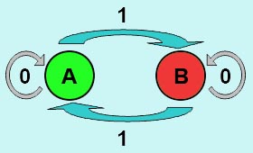
| - | The logic principle of our design is shown above. Unless the input signal transfer from one stable condition to another (such as 0 to 1 or 1 to 0), the output signal would change into 1, otherwise it would maintain 0. Thus, the immediate response to emergency (input change) enables our design to detect signal variation in a short time, which is beneficial | + | The logic principle of our design is shown above. Unless the input signal transfer from one stable condition to another (such as 0 to 1 or 1 to 0), the output signal would change into 1, otherwise it would maintain 0. Thus, the immediate response to emergency (input change) enables our design to detect signal variation in a short time, which is beneficial to the control of biological systems. |
| - | + | ||
| - | + | ||
<br><br> | <br><br> | ||
| - | <table width=" | + | <font size="3" color="#0099CC">'''2.'''</font>[[Tianjin/FLIP-FLOP/Design1|<font size="3" color="#0099CC">'''Construction of Biological Circuit'''</font>]] |
| + | <br><br> | ||
| + | <table width="79%" border="10" cellpadding="0" cellspacing="0" style="padding: 10px; background-color: #FFFF99"> | ||
<tr> | <tr> | ||
<td><center>[[Image:Flip-Flop.gif]]</center></td> | <td><center>[[Image:Flip-Flop.gif]]</center></td> | ||
</tr></table> | </tr></table> | ||
|- | |- | ||
| - | |width="960px" style="padding: 10px; background-color: # | + | |width="960px" style="padding: 10px; background-color: #FFFF66" | |
==<font size="4" color="#0000CC">Modeling</font>== | ==<font size="4" color="#0000CC">Modeling</font>== | ||
| - | + | Mainly based on Ordinary Differential Equations, a mathematical model of our Flip-Flop | |
| - | system to test the result of our design and predict potential key factors deciding the results | + | system is constructed to test the result of our design and predict potential key factors deciding the results |
of our experiment. According to the model, the variation of output signal responding to the input signal matches the typical | of our experiment. According to the model, the variation of output signal responding to the input signal matches the typical | ||
| - | feature of | + | feature of Flip-Flop, and there would be no output signal unless at the positive edge and negative edge of the input signal. The influence of |
| - | AHL to the output signal is also considered. By changing the degradation | + | AHL to the output signal is also considered. By changing the degradation rate of AHL, the fluorescence intensity |
| - | + | exhibits different behaviour which could be explained by principles of Flip-Flop. Finally, the parameter sensitivity is also tested to | |
| - | explore most significant | + | explore most significant parameters to output signals and it is discovered that the strength of promoter I, which controls the production of LuxI, the |
promoter II, which controls the expression of LuxR, exert great effect on the final results. | promoter II, which controls the expression of LuxR, exert great effect on the final results. | ||
| Line 52: | Line 52: | ||
<font size="3" color="#0099CC">'''1.'''</font> | <font size="3" color="#0099CC">'''1.'''</font> | ||
| - | [[Tianjin/FLIP-FLOP/More details |<font size="3" color="#0099CC">'''Ligation Strategy'''</font>]] | + | [[Tianjin/FLIP-FLOP/More details |<font size="3" color="#0099CC">'''Ligation Strategy'''</font>]]<br> |
| - | <br> | + | |
<table width="99%" border="0" cellpadding="0" cellspacing="10" style="padding: 10px; background-color: #FFFF99"> | <table width="99%" border="0" cellpadding="0" cellspacing="10" style="padding: 10px; background-color: #FFFF99"> | ||
| - | |||
<td><center>[[Image:TJUzmlligation.jpg|300px]] </td> | <td><center>[[Image:TJUzmlligation.jpg|300px]] </td> | ||
<td><div id="Experiment"> | <td><div id="Experiment"> | ||
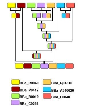
| - | In order to assemble our device genetically in the shortest period, we | + | In order to assemble our device genetically in the shortest period, we tried different method-Rolling Assembly and Parallel Assembly at the same time. |
<ul> | <ul> | ||
| - | <li>E.coli | + | <li>E.coli Cultivation</li> |
<li>Plasmid Extraction</li> | <li>Plasmid Extraction</li> | ||
<li>Verification</li> | <li>Verification</li> | ||
| Line 77: | Line 75: | ||
<font size="3" color="#0099CC">'''3.'''</font>[[Tianjin/FLIP-FLOP/Experiment/result|<font size="3" color="#0099CC">'''Experimental Result'''</font>]] | <font size="3" color="#0099CC">'''3.'''</font>[[Tianjin/FLIP-FLOP/Experiment/result|<font size="3" color="#0099CC">'''Experimental Result'''</font>]] | ||
<br><br> | <br><br> | ||
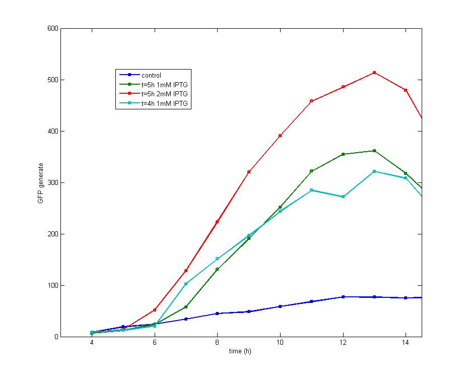
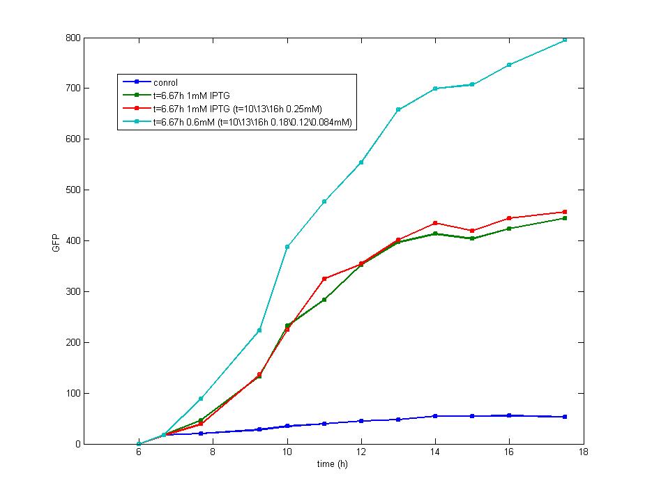
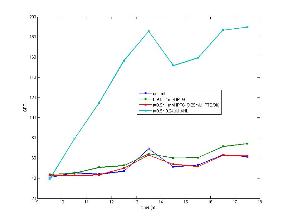
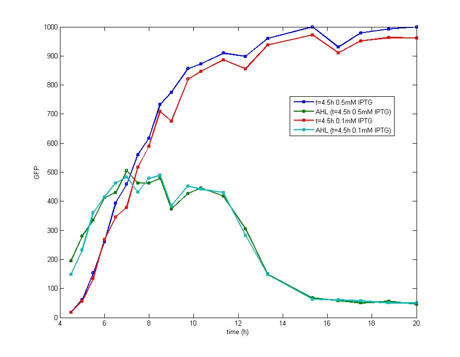
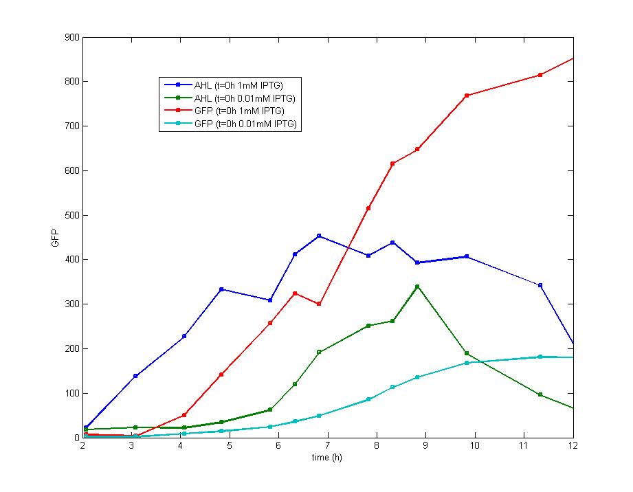
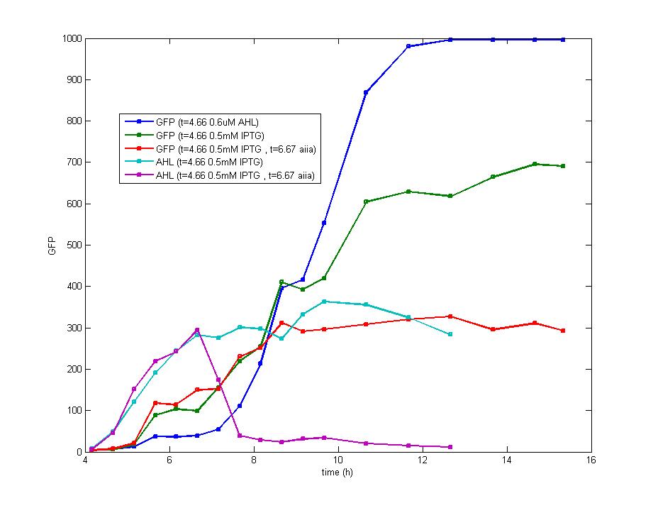
| - | <font size="2" color="#000000"> | + | <font size="2" color="#000000">Considering the significance of IPTG impulse as the input signal, we designed a series of experiments to search for the most suitable condition to produce legible output signals, including the concentration of IPTG |
| - | ([[high]] and [[low]] input signal), the time point for addition( exponential phase and stationary phase) and supplement of IPTG. The optimal plan is to add 0.5mM IPTG during the early exponential phase of E.coli cells, and the output signal together with other parameters have been summarized on the same graph which proves that every part of our device works as well as we expected. The slow | + | ([[high]] and [[low]] input signal), the time point for addition( exponential phase and stationary phase) and supplement of IPTG. The optimal plan is to add 0.5mM IPTG during the early exponential phase of E.coli cells, and the output signal together with other parameters have been summarized on the same graph which proves that every part of our device works as well as we expected. The slow degradation rate of Green Fluorescence Protein leaves our device some space to improve to achieve a more desirable result.</font><br><br> |
| - | + | ||
| - | + | ||
| + | <table width="100%" style="background-color:#FFFF99;padding:5px;text-align:center;"><tr> | ||
| + | <td>[[Image:tjuexpff201.jpg|290px]]</td> | ||
| + | <td>[[Image:tjuexpff202.jpg|305px]]</td> | ||
| + | <td>[[Image:tjuexpff203.jpg|305px]]</td> | ||
| + | </tr> | ||
| + | </table> | ||
| - | | | + | <table width="100%" style="background-color:#FFFF99;padding:5px;text-align:center;"><tr> |
| + | <td>[[Image:tjuexpff204.jpg|298px]]</td> | ||
| + | <td>[[Image:tjuexpff205.jpg|305px]]</td> | ||
| + | <td>[[Image:tjuexpff206.jpg|305px]]</td> | ||
| + | </tr> | ||
| + | </table> | ||
Latest revision as of 03:53, 27 October 2007
DesignFlip-Flop, a huge family of basic electric elements, is widely applied to the field of electric circuit and construction of database. One of the most common members of this family is RS Flip-Flop, the key part of which is a clock-controlled element. Based on the the “Latch and Enable Control" conception of "Flip-Flop" and synthetic biology, we designed the Genetical RS Flip-Flop whose output signal (Green Fluorescence protein) is regulated by input signal (the addition of IPTG). Besides, we modulate the performance of Genetical RS FLIP-FLOP to optimize our original design. 1.Introduction to the Logic Rules of Our Flip-Flop
The logic principle of our design is shown above. Unless the input signal transfer from one stable condition to another (such as 0 to 1 or 1 to 0), the output signal would change into 1, otherwise it would maintain 0. Thus, the immediate response to emergency (input change) enables our design to detect signal variation in a short time, which is beneficial to the control of biological systems.
| ||||||
ModelingMainly based on Ordinary Differential Equations, a mathematical model of our Flip-Flop system is constructed to test the result of our design and predict potential key factors deciding the results of our experiment. According to the model, the variation of output signal responding to the input signal matches the typical feature of Flip-Flop, and there would be no output signal unless at the positive edge and negative edge of the input signal. The influence of AHL to the output signal is also considered. By changing the degradation rate of AHL, the fluorescence intensity exhibits different behaviour which could be explained by principles of Flip-Flop. Finally, the parameter sensitivity is also tested to explore most significant parameters to output signals and it is discovered that the strength of promoter I, which controls the production of LuxI, the promoter II, which controls the expression of LuxR, exert great effect on the final results. 1. Construction of Mathematical Model
| ||||||
Experiment2.
Parts Reservoir
|
