ETHZ/Intro Tim
From 2007.igem.org
(Difference between revisions)
(→'''.:: System Explanation ::.''') |
(→'''.:: System Explanation ::.''') |
||
| Line 1: | Line 1: | ||
=='''.:: System Explanation ::.'''== | =='''.:: System Explanation ::.'''== | ||
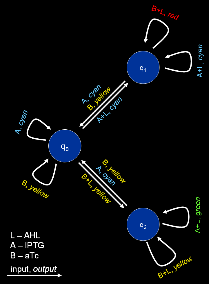
| - | [[Image:FSM.png|thumb| | + | [[Image:FSM.png|thumb|350px|Figure 1: Graph representing the finite state machine.]] |
The proposed system is best described by a [http://en.wikipedia.org/wiki/Mealy_machine Mealy machine], a special type of [http://en.wikipedia.org/wiki/Finite_state_machine finite state machines] (FSM). Mealy machines are defined by a 6-tuple, (''Q'', ''q''<sub>0</sub>, Σ, Λ, ''δ'', ''Ω''), with: | The proposed system is best described by a [http://en.wikipedia.org/wiki/Mealy_machine Mealy machine], a special type of [http://en.wikipedia.org/wiki/Finite_state_machine finite state machines] (FSM). Mealy machines are defined by a 6-tuple, (''Q'', ''q''<sub>0</sub>, Σ, Λ, ''δ'', ''Ω''), with: | ||
* ''Q'' - a set of states, for the proposed system we use three different states (''q''<sub>0</sub> - not yet trained, ''q''<sub>1</sub> - trained to recognize chemical A, ''q''<sub>2</sub> - trained to recognize chemical B) | * ''Q'' - a set of states, for the proposed system we use three different states (''q''<sub>0</sub> - not yet trained, ''q''<sub>1</sub> - trained to recognize chemical A, ''q''<sub>2</sub> - trained to recognize chemical B) | ||
Revision as of 09:32, 18 October 2007
.:: System Explanation ::.
The proposed system is best described by a [http://en.wikipedia.org/wiki/Mealy_machine Mealy machine], a special type of [http://en.wikipedia.org/wiki/Finite_state_machine finite state machines] (FSM). Mealy machines are defined by a 6-tuple, (Q, q0, Σ, Λ, δ, Ω), with:
- Q - a set of states, for the proposed system we use three different states (q0 - not yet trained, q1 - trained to recognize chemical A, q2 - trained to recognize chemical B)
- q0 - a start state, here we assume we start in a state where the system is not yet trained
- Σ = {A+L, A, B+L, B} - an input alphabet
- Λ = {green, red, blue, yellow} - an output alphabet
- δ : Q × Σ → Q - a state transition function
- Ω : Q × Σ → Λ - an output function
In detail, the transition function δ and the output function Ω look as follows:
| inputs/states | q0 | q1 | q2 | inputs/states | q0 | q1 | q2 | |
|---|---|---|---|---|---|---|---|---|
| A+L | q1 | q1 | q1 | A+L | green | green | blue | |
| A | q0 | q0 | q0 | A | green | green | green | |
| B+L | q2 | q2 | q2 | B+L | yellow | red | yellow | |
| B | q0 | q0 | q0 | B | yellow | yellow | yellow |
The resulting automaton is represented by Fig. 1.
