ETHZ/Simulation
From 2007.igem.org
(→Simulation of Test Cases) |
(→Simulation of Test Cases) |
||
| Line 21: | Line 21: | ||
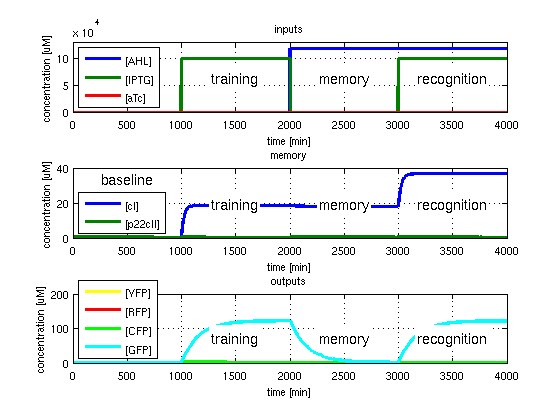
<p>[[Image:ETHZTest1.png|left|thumb|<b>Fig. 2</b>: Learn and recognize IPTG. The simulated behavior of the system, when IPTG is presented both during the learning phase, and the recognition phase. In both the learning and recognition phase, the system reports by producing green florescent proteins, which matches the desired behavior. |420px]] | <p>[[Image:ETHZTest1.png|left|thumb|<b>Fig. 2</b>: Learn and recognize IPTG. The simulated behavior of the system, when IPTG is presented both during the learning phase, and the recognition phase. In both the learning and recognition phase, the system reports by producing green florescent proteins, which matches the desired behavior. |420px]] | ||
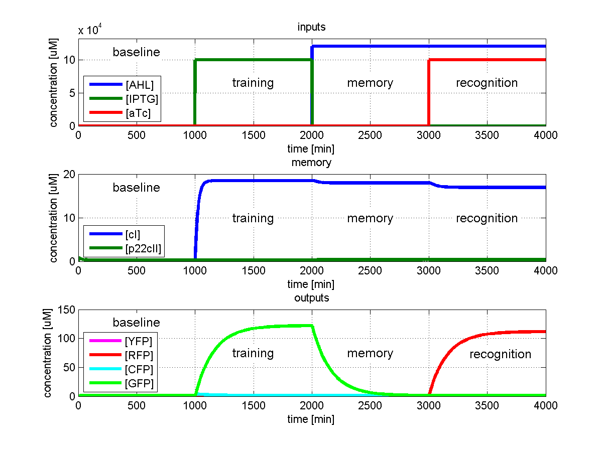
| - | [[Image:ETHZTest2.png|thumb|<b>Fig. 3</b>: Learn IPTG and get tested for aTc. The simulated behavior of the system, when IPTG is presented during the learning phase, and is presented aTc during the recognition phase. | + | [[Image:ETHZTest2.png|thumb|<b>Fig. 3</b>: Learn IPTG and get tested for aTc. The simulated behavior of the system, when IPTG is presented during the learning phase, and is presented aTc during the recognition phase. The system reports by producing red fluorescent proteins during the recognition phase, which matches the desired behavior. |420px]] |
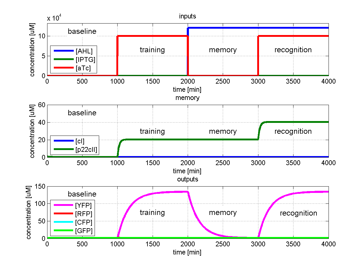
[[Image:ETHZTest3.png|left|thumb|<b>Fig. 4</b>: Learn and recognize aTc. The simulated behavior of the system, when aTc is presented both during the learning phase and the recognition phase. In both the learning and recognition phase the system reports by producing yellow fluorescent proteins, which matches the desired behavior. |420px]] | [[Image:ETHZTest3.png|left|thumb|<b>Fig. 4</b>: Learn and recognize aTc. The simulated behavior of the system, when aTc is presented both during the learning phase and the recognition phase. In both the learning and recognition phase the system reports by producing yellow fluorescent proteins, which matches the desired behavior. |420px]] | ||
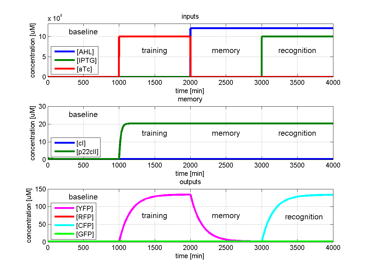
[[Image:ETHZTest4.png|right|thumb|<b>Fig. 5</b>: Learn aTc and get tested for IPTG. The simulated behavior of the system, when aTc is presented during the learning phase, and IPTG is presented during the recognition phase. In contrast to Fig. 4, the system reports by producing cyan florescent proteins during the recognition phase, which matches the desired behavior. |420px]]</p> | [[Image:ETHZTest4.png|right|thumb|<b>Fig. 5</b>: Learn aTc and get tested for IPTG. The simulated behavior of the system, when aTc is presented during the learning phase, and IPTG is presented during the recognition phase. In contrast to Fig. 4, the system reports by producing cyan florescent proteins during the recognition phase, which matches the desired behavior. |420px]]</p> | ||
Revision as of 12:49, 21 October 2007

Simulating the EducatETH E. coli System
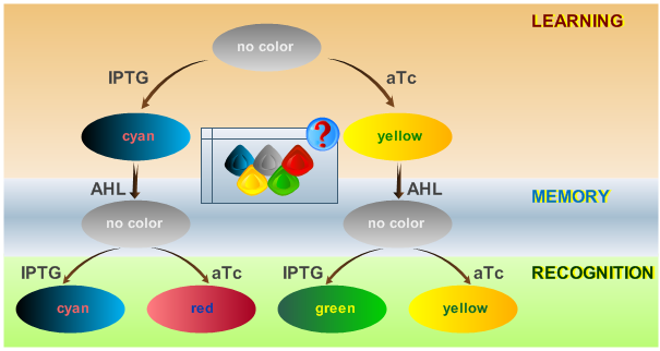
As has been presented in the Modeling page, we have created a model of our system, that can be described as a finite state machine. In order to examine our system's behavior thoroughly, we have to simulate it through all the difference phases that can be reached. We carry out our simulations based on the protocol presented in Fig. 1.
Simulation of Test Cases
To test all the possible conditions and transitions in our system, we run timing simulations for all 4 different branches in the flow diagram of our protocol, and we plot the concentrations of the inducers, memory proteins and reporter proteins. During each learning, memorizing and recognizing phase, we wait for the steady state of the system to be reached. The three phases of the system are thus separated sufficiently in time. In all the cases, we follow the following procedure:
- During the first 1000 minutes of the simulation, we do not add any inducers to the system, and as a result, we check for the baseline production of proteins.
- Between 1000 and 2000 minutes, we add the inducer that should be learned, and we let the system reach steady state.
- After the 2000th minute, we add the inducer AHL for memory formation, and run the simulation for an additional 1000 minutes, to reach again steady state.
- Between 3000 and 4000 minutes, we tested the final behavior of the system, and we check if it reacts in the desired way, by showing the appropriate color.
The parameters of the system are crucial if one wants to have accurate and realistic simulations. We present the parameters that we used to simulate our system, in the section Parameters.
