USTC/Logic-Gate Promoters
From 2007.igem.org
m (→Schemes of Bio-Logic Promoters) |
m (→Schemes of Bio-Logic Promoters) |
||
| Line 41: | Line 41: | ||
{| border="1" | {| border="1" | ||
|- | |- | ||
| - | | Scheme | + | |align="center"| Scheme |
| - | | Test-environment | + | |align="center"| Test-environment |
| - | | Results | + | |align="center"| Results |
| - | | Comments | + | |align="center"| Comments |
|- | |- | ||
| [[Image:USTC_NANDv1.png|380px]] | | [[Image:USTC_NANDv1.png|380px]] | ||
| - | | [[Image:USTC_RM_LacI_LRLa.png|92px]] | + | |align="center"| [[Image:USTC_RM_LacI_LRLa.png|92px]] |
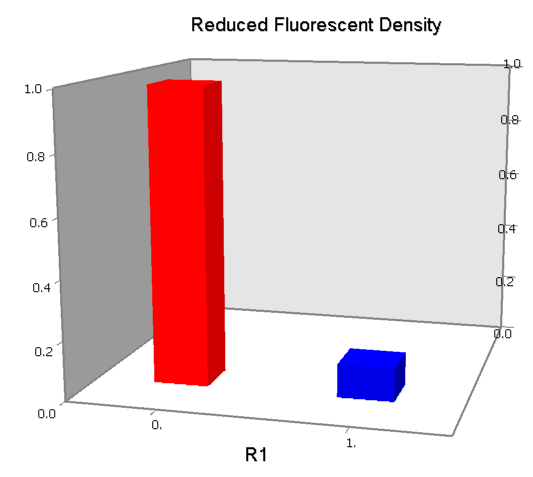
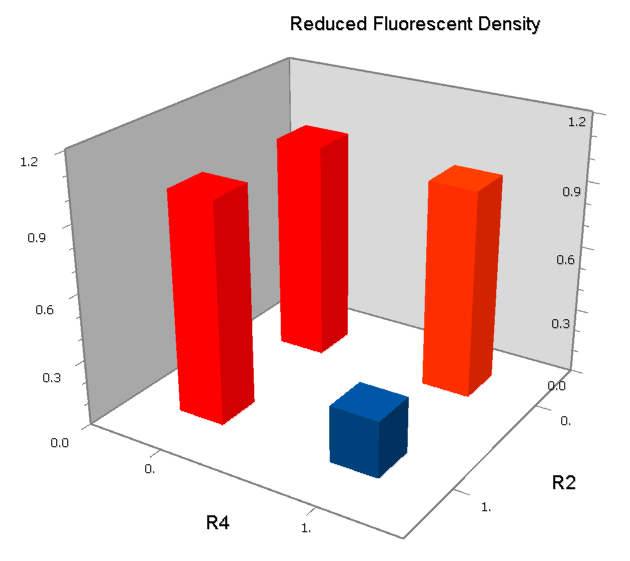
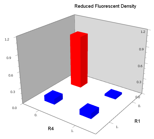
| - | | [[Image:USTC_NANDv1_Data.png|93px]] | + | |align="center"| [[Image:USTC_NANDv1_Data.png|93px]] |
| Interference between inputs | | Interference between inputs | ||
|- | |- | ||
| [[Image:USTC_NORv1.png|380px]] | | [[Image:USTC_NORv1.png|380px]] | ||
| - | | [[Image:USTC_RM_LacI_LRLa.png|92px]] | + | |align="center"| [[Image:USTC_RM_LacI_LRLa.png|92px]] |
| - | | [[Image:USTC_NORv1_Data.png|93px]] | + | |align="center"| [[Image:USTC_NORv1_Data.png|93px]] |
| Interference between inputs | | Interference between inputs | ||
|- | |- | ||
| [[Image:USTC_NOTv1.png|380px]] | | [[Image:USTC_NOTv1.png|380px]] | ||
| - | | [[Image:USTC_RM_LacI.png|64px]] | + | |align="center"| [[Image:USTC_RM_LacI.png|64px]] |
| - | | [[Image:USTC_NOTv1_Data.png|93px]] | + | |align="center"| [[Image:USTC_NOTv1_Data.png|93px]] |
| <font color="red">Works</font> | | <font color="red">Works</font> | ||
|- | |- | ||
| [[Image:USTC_NANDv2a.png|380px]] | | [[Image:USTC_NANDv2a.png|380px]] | ||
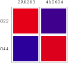
| - | | [[Image:USTC_RM_ARL4A0604_ARL2A0203.png|92px]] | + | |align="center"| [[Image:USTC_RM_ARL4A0604_ARL2A0203.png|92px]] |
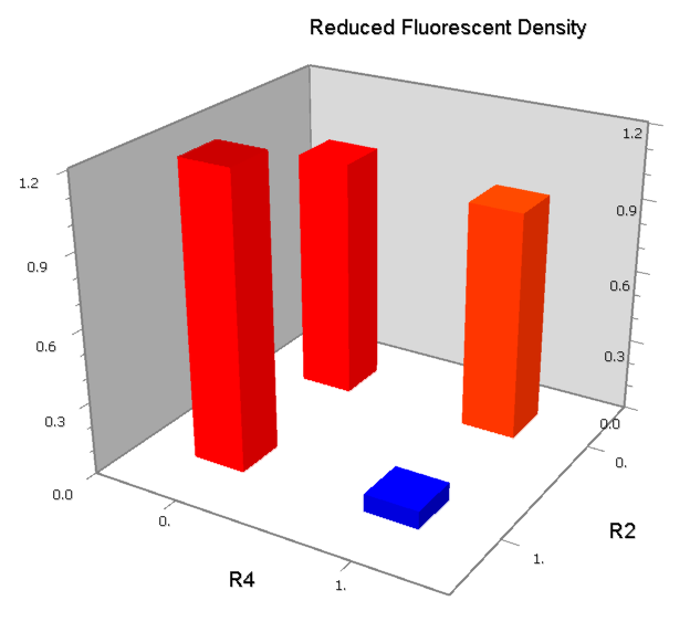
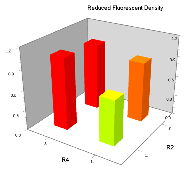
| - | | [[Image:USTC_NANDv2a_Data.png|93px]] | + | |align="center"| [[Image:USTC_NANDv2a_Data.png|93px]] |
| <font color="orange">Works</font><BR>But with slight downstream repression | | <font color="orange">Works</font><BR>But with slight downstream repression | ||
|- | |- | ||
| [[Image:USTC_NANDv2b.png|380px]] | | [[Image:USTC_NANDv2b.png|380px]] | ||
| - | | [[Image:USTC_RM_ARL4A0604_ARL2A0203.png|92px]] | + | |align="center"| [[Image:USTC_RM_ARL4A0604_ARL2A0203.png|92px]] |
| - | | Failed in X-gal Assay | + | |align="center"| Failed in X-gal Assay |
| Downstream operator is too weak | | Downstream operator is too weak | ||
|- | |- | ||
| [[Image:USTC_NORv1.png|380px]] | | [[Image:USTC_NORv1.png|380px]] | ||
| - | | [[Image:USTC_RM_ARL4A0604_ARL2A0203.png|92px]] | + | |align="center"| [[Image:USTC_RM_ARL4A0604_ARL2A0203.png|92px]] |
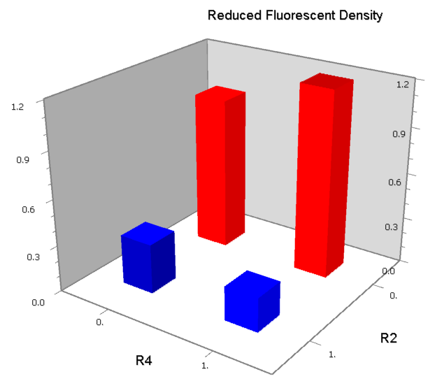
| - | | [[Image:USTC_NORv1_Data2.png|93px]] | + | |align="center"| [[Image:USTC_NORv1_Data2.png|93px]] |
| Inefficacy of upstream operator | | Inefficacy of upstream operator | ||
|- | |- | ||
| [[Image:USTC_NANDv3a.png|380px]] | | [[Image:USTC_NANDv3a.png|380px]] | ||
| - | | [[Image:USTC_RM_ARL4A0604_ARL2A0203.png|92px]] | + | |align="center"| [[Image:USTC_RM_ARL4A0604_ARL2A0203.png|92px]] |
| - | | [[Image:USTC_NANDv3a_Data.png|93px]] | + | |align="center"| [[Image:USTC_NANDv3a_Data.png|93px]] |
| Co-repression is too weak<BR>Downstream solo-repression is to strong | | Co-repression is too weak<BR>Downstream solo-repression is to strong | ||
|- | |- | ||
| [[Image:USTC_NANDv3b.png|380px]] | | [[Image:USTC_NANDv3b.png|380px]] | ||
| - | | [[Image:USTC_RM_ARL4A0604_ARL2A0203.png|92px]] | + | |align="center"| [[Image:USTC_RM_ARL4A0604_ARL2A0203.png|92px]] |
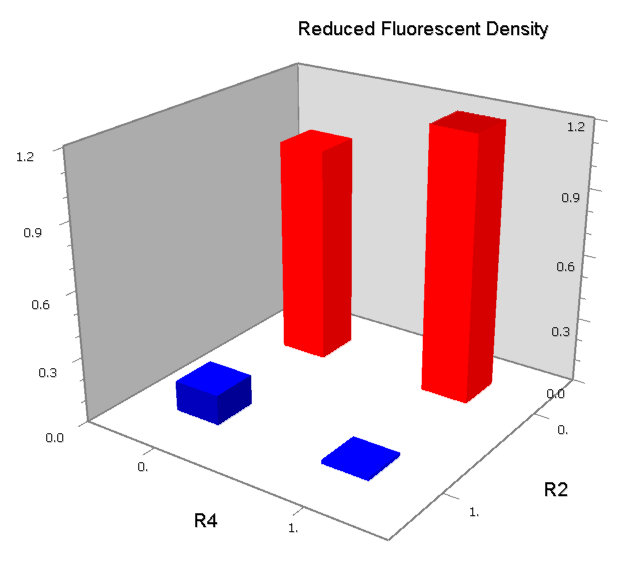
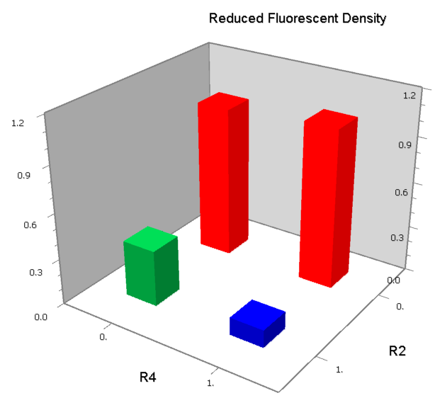
| - | | [[Image:USTC_NANDv3b_Data.png|93px]] | + | |align="center"| [[Image:USTC_NANDv3b_Data.png|93px]] |
| <font color="red">Works</font> | | <font color="red">Works</font> | ||
|- | |- | ||
| [[Image:USTC_NORv2.png|380px]] | | [[Image:USTC_NORv2.png|380px]] | ||
| - | | [[Image:USTC_RM_ARL4A0604_ARL2A0203.png|92px]] | + | |align="center"| [[Image:USTC_RM_ARL4A0604_ARL2A0203.png|92px]] |
| - | | [[Image:USTC_NORv2_Data.png|93px]] | + | |align="center"| [[Image:USTC_NORv2_Data.png|93px]] |
| Inefficacy of upstream operator | | Inefficacy of upstream operator | ||
|- | |- | ||
| [[Image:USTC_NANDv4.png|380px]] | | [[Image:USTC_NANDv4.png|380px]] | ||
| - | | [[Image:USTC_RM_ARL4A0604_ARL2A0203.png|92px]] | + | |align="center"| [[Image:USTC_RM_ARL4A0604_ARL2A0203.png|92px]] |
| - | | [[Image:USTC_NANDv4_Data.png|93px]] | + | |align="center"| [[Image:USTC_NANDv4_Data.png|93px]] |
| Hybrid operator do not work as expected | | Hybrid operator do not work as expected | ||
|- | |- | ||
| [[Image:USTC_NORv3.png|380px]] | | [[Image:USTC_NORv3.png|380px]] | ||
| - | | [[Image:USTC_RM_ARL4A0604_LacI.png|92px]] | + | |align="center"| [[Image:USTC_RM_ARL4A0604_LacI.png|92px]] |
| - | | [[Image:USTC_NORv3_Data.png|93px]] | + | |align="center"| [[Image:USTC_NORv3_Data.png|93px]] |
| <font color="red">Works</font> | | <font color="red">Works</font> | ||
|- | |- | ||
Revision as of 08:26, 24 October 2007
Contents |
Cis-acting Bio-Logic Gates
In natural cells, combinational logic computation can be carried out by cis-acting elements []. Theoretically, dual repressors interacting on two adjacent operators can generate complex logic function as NAND, NOT and NOT []. But seldom of the parameters of these models have been measured, and practical artificial logic promoters are hard to made because of the lack of appropriate inputs. In this project, we simplify these models to reduce the number of parameters, use artificial high-specific repressors based-on Lac repressor as inputs, predict possible pattern of logic promoters, construct and test them experimentally, to attempt to find a systematical way to construct cis-acting bio-logic promoters. As the results, a piece of DNA about 60 – 200bp is able to be built up and to act as a logic gate.
Advatanges of Cis-acting Bio-Logic Gates
- Work in vivo and can be genetically inherited
- Can be systematically built up according to several patterns
- Small in scale
- About 2.0nm in width, 20 - 70nm in length, similar to transistors in present VSLI in size[], sometimes even smaller
- Can be cascaded to implement any complex combinational logic computation
- And is also able to form sequential circuit
Repression Model
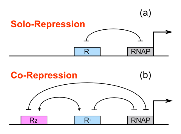
Lacramioara Bintu et al. have reported a simple thermodynamic model which can quantitatively describe promoter activity under one or more regulator factors. In this project, we focus on fold-change under one or two repressors, which means the ratio of promoter activity in the absence and presence of repressor. For a weak promoter, the fold-change can be written approximately as a function of repressor concentrations, inter-operator distances, repressor–operator affinity and repressor-repressor interactions.
For a promoter containing a single operator site shown in Figure 1(a), the fold-change is given as:
For a promoter containing two different operators, of which the relative repressors may be able to interact with each other shown in Figure 1(b), the fold-change is given as:
Concerning a NOT gate which works under approximate equal high and low repressor concentration, Rlow=0 and Rhigh=RH, its performance can be expressed simply as NOT score in a non-dimension form:
In the same way, NAND factor and NOR factor are:
Schemes of Bio-Logic Promoters
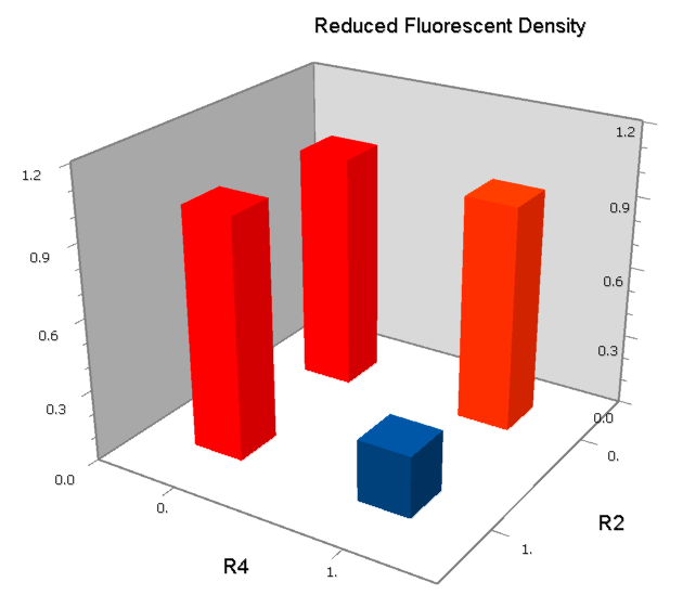
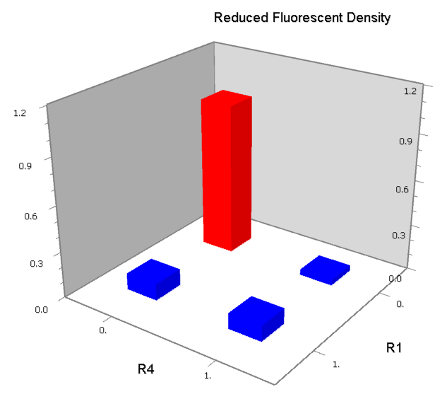
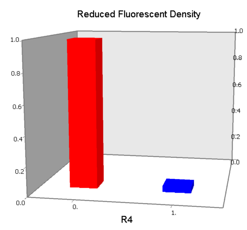
Dozens of potential bio-logic patterns were experimentally synthesized and tested in solo-repression or co-repression test-bench. Some representative ones are shown and commented as following.
Repression Assay
Build Up Promoter Family
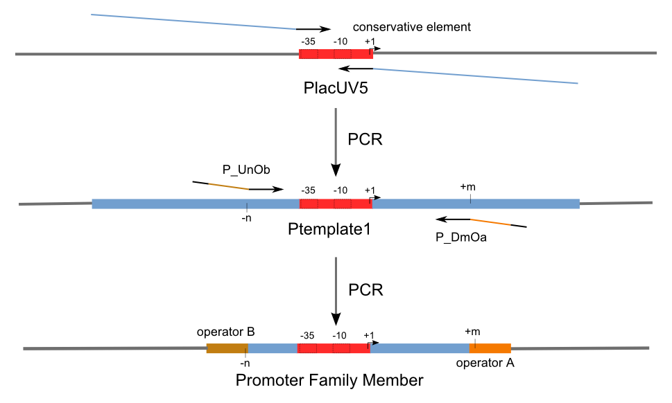
Firstly, we extend both sides of the conservative region for transcriptional initiation of PlacUV5[], including -35 box,-10 box and +1 starting point, with two non-sense sequence selected from random groups. The product is named as P_template1 as it is the template for the promoter family. These two non-sense sequence have three main characters:
- They will never include the restriction enzyme cutting sites that will be involved in the whole study;
- They will never include the recognition sites of RNA Polymerases and those of either of the two repressors;
- They will never present in complicated structures.
Secondly, another group of primers, of which the elongation region at 5’ end may contain a unique operator sequence or each, is applied at both ends of P_template1, equipping us with an according group of promoters with complete structures. These promoters can include variant operator sequences at different position in flank of the conservative region.
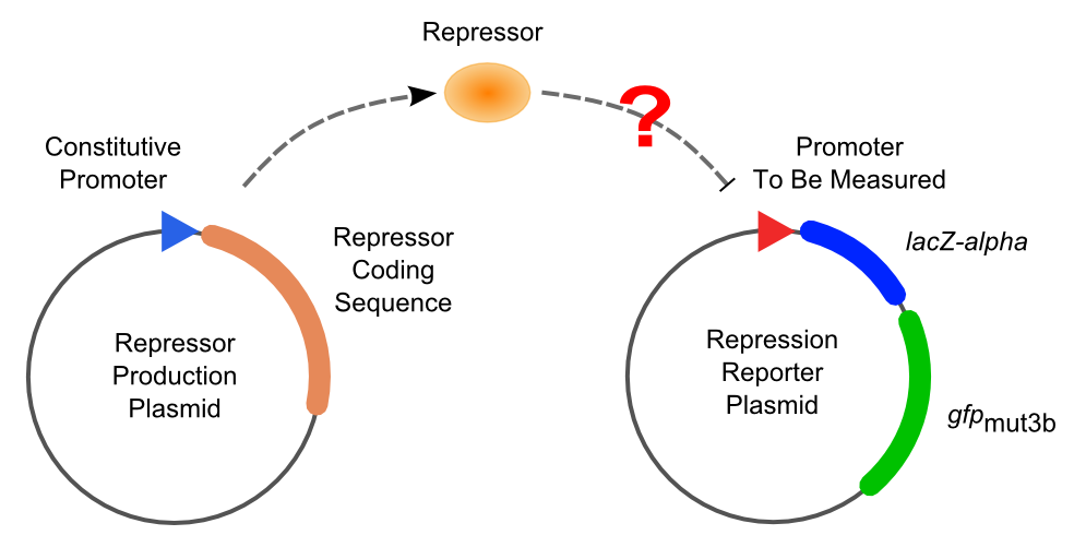
Then the promoter fragments are digested with XbaI and BamHI and cloned into repression-reporter plasmid, which contains lacZ alpha fragment and gfp under the promoter insertion site.
Solo-Repression Assay
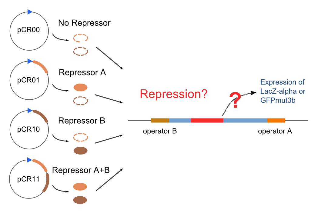
Co-Repression Assay
Final Results
