Tianjin/FLIP-FLOP/Model11
From 2007.igem.org
(Difference between revisions)
Lovecarrot (Talk | contribs) |
Sunlovedie (Talk | contribs) |
||
| Line 1: | Line 1: | ||
{| | {| | ||
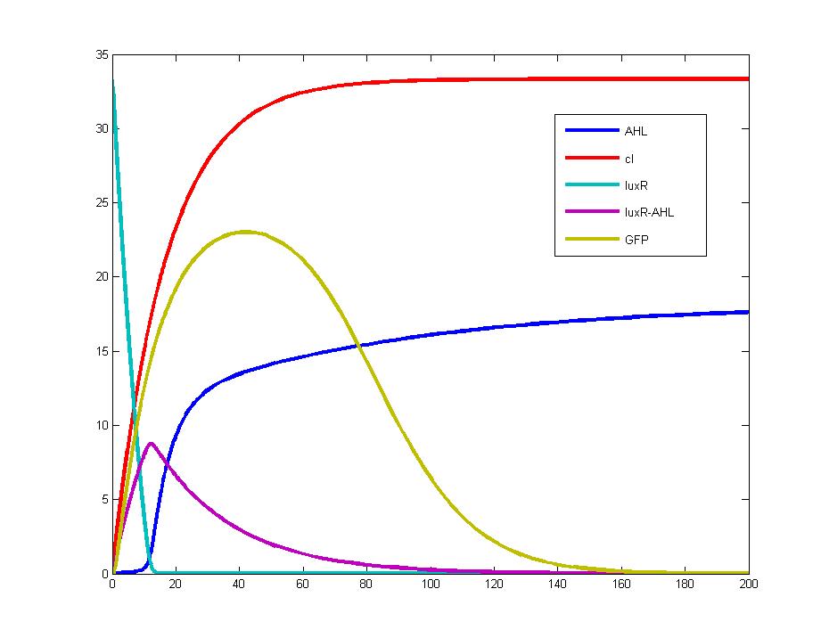
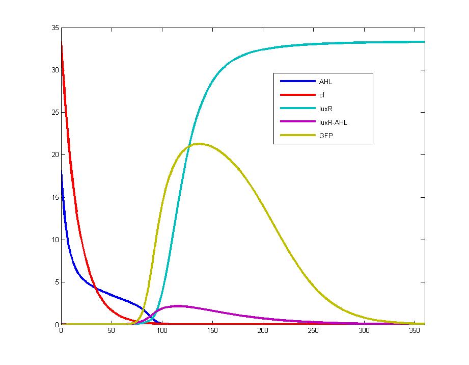
| - | These two pictures are | + | These two pictures are drawn with the same parameters coming from related literature. Both figures point out that the output signal (GFP, yellow line) will form a pulse immediately after the input signal alters. |
<br> | <br> | ||
| - | Figure 1: This figure shows the concentration variation of chemical | + | Figure 1: This figure shows the concentration variation of chemical molecules when the input signal is at positive edge when t=0. |
[[Image:tjumodel11a.jpg|500px]]<br> | [[Image:tjumodel11a.jpg|500px]]<br> | ||
<br> | <br> | ||
| - | Figure 2: This figure shows the concentration variation of chemical | + | Figure 2: This figure shows the concentration variation of chemical molecules when the input signal is at negative edge when t=0. |
[[Image:tjumodel11b.jpg|500px]]<br> | [[Image:tjumodel11b.jpg|500px]]<br> | ||
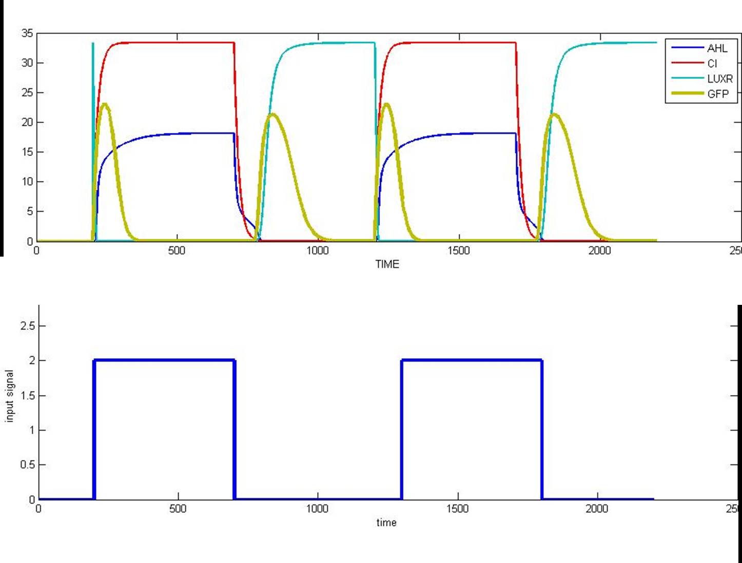
| - | Figure 3: This graph shows the variation of AHL,cI,LuxR and GFP responding to the addition of input | + | Figure 3: This graph shows the variation of AHL, cI, LuxR and GFP responding to the addition of input |
signal(IPTG). It is easy to find that the level of AHL and cI shares the same changing tendency | signal(IPTG). It is easy to find that the level of AHL and cI shares the same changing tendency | ||
with that of IPTG, whereas the contents of LuxR protein changes inversely with that of IPTG. | with that of IPTG, whereas the contents of LuxR protein changes inversely with that of IPTG. | ||


