Project
From 2007.igem.org
(→Molecular Mechanism) |
|||
| Line 197: | Line 197: | ||
</td></tr></table> | </td></tr></table> | ||
<center> | <center> | ||
| - | [[Waterloo | Home ]] | + | [[Waterloo | Home ]] | [[Project | Project]] | [[Modelling | Mathematical Modelling]] | [[Construction_&_Testing | Construction & Testing]] | [[Extensions | Future Work]] |
</center> | </center> | ||
Revision as of 19:10, 26 October 2007
Contents |
Background
Binary Addition
| Decimal (Base 10) |
Binary (Base 2) |
0 |
00 |
1 |
01 |
2 |
10 |
3 |
11 |
4 |
100 |
5 |
101 |
6 |
110 |
When working in binary, only two digits are used: 0 and 1. A single binary digit is called a bit. Counting proceeds as: To add two binary numbers, the process is much the same as adding two decimal (ordinary) numbers, except that instead of carrying when two digits add to ten, carrying must be performed when two digits add to two. In other words, 0 + 1 adds to 1, but 1 + 1 adds to 0 with a carry of 1, which gives 10 (just as in decimal 1 + 9 would add to 0 with a carry of 1, to give 10). A complete list of the possibilities is as follows:
Here is an example of long addition:
Half-Adder vs. Full-Adder
Any construct designed to add two numbers will either be a half-adder or a full-adder. A half-adder can only add together two single digits, whereas a full-adder is needed to add two numbers consisting of more than one digit.
For example, a half-adder could perform the addition 1 + 0 = 1, or 1 + 1 = 10, but it would take a full-adder to be able to perform 1100101 + 100101.
In terms of implementation, a half-adder accepts two inputs (the two digits to be summed) and returns two outputs (the "sum bit" and the "carry bit"). To add 1 + 1, the two inputs would each be 1, the sum bit would be 0, and the carry bit would be 1. A full list of the possibilities is shown in Figure 1.
A full-adder is merely a half-adder that accepts an extra input; namely, the carry bit from another full-adder. Each full-adder is responsible for adding one pair of corresponding digits from the two numbers to be added, and it must add to that the carry bit from the previous full-adder. The full-adder will output the resulting sum bit and carry bit, and the process will continue until all the digits have been added. Such a chain of full-adders is called a ripple carry adder. See Figure 2 for a full list of possibilities.
Logic Gates and Implementing an Adder
A logic gate performs a logical operation on one or more logic inputs and produces a logic output. Usually the inputs and outputs are binary, meaning they each have a value of either 0 or 1. Also, it is often useful to think of of 0 as representing "false", and 1 as representing "true". A list of relevant logic gates is as follows:
- OR gate
- XOR gate
- AND gate
- NOT gate
For the following explanations, A and B represent statements that can be either true or false.
| Operator | Condition | Truth Table |
| a OR b | If a, b, or both are true | 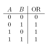 |
| a XOR b | If a and b are different | 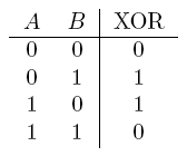 |
| AND | If both are true | 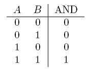 |
| NOT a | If a is false | 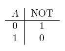 |
Using logic gates to make an adder
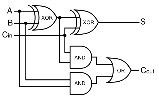
Given two binary inputs A and B, their sum can be computed by passing these inputs through various logic gates. The process is illustrated in Figures 4 and 5.
DNA as Logic Gates
Our project focuses on using DNA as logic gates. The output of a logical operation is the protein product of a certain gene; the inputs are external stimuli that cause allosteric changes in the conformation of proteins that can induce or inhibit transcription by acting on promoter elements. Whether or not the gene is turned 'on' or 'off' depends on the logic gate implemented.
For example, consider a positively-regulated gene G that codes for protein X. By default, the gene is not expressed (to be precise, there is a low basal level of expression that we can disregard). If the inputs A and B are on and together can turn on expression of gene G, the expressed protein X represents the output of an AND gate. The inputs would be the "presence" or "absence" of A and the "presence" or "absence" of B (both representing 0 and/or 1 as inputs), and the output would be the "presence" or "absence" of X (where "presence" and "absence" should be read as high and low intensity/concentration, respectively).
Alternatively, consider a negatively regulated gene H that codes for protein Y. By default, the
This is the type of approach used to construct our biological adder. Further details are given under the Project Details section.
Project Details
Input and Output
As a half-adder, our device requires two binary inputs; the possible 1 and 0 values of these inputs are represented by the presence and absence of two stimuli. For the first input, the presence of red light represents a 0 and the absence represents a 1. For the second input, the absence of tetracycline represents a 0 and the presence represents a 1.
We chose to use light as an input because it does not require altering the media, it can be turned on and off rapidly, and it has extremely high resolution and accuracy. The red light will be detected by Cph8, the previously used Cph1/EnvZ fusion protein.
Tetracycline was used as a second input since it inactivates the repressor TetR, thereby derepressing expression at the PtetR locus.
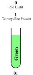
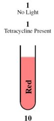
Depending on the result of the calculation, the bacteria will produce either red fluorescent protein (RFP), green fluorescent protein (GFP), or neither. A diagram of the biological half adder in culture is shown above, depicting the possible outcomes for each combination of inputs.
Molecular Mechanism
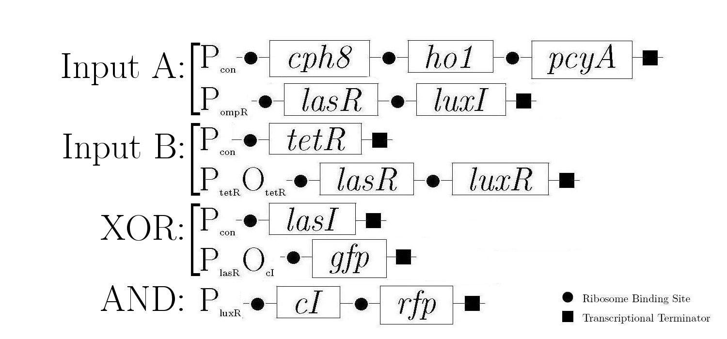
As components of a natural quorum sensing system, LuxR and LuxI proteins are ideal for producing the AND logic function required to create 1-bit half-adder. LuxR enhances transcription at Plux when activated by an inducer produced by LuxI. The expression of both LuxR and LuxI is therefore necessary to "turn on" the promoter Plux. LasR and LasI have analogous roles in another quorum sensing system, and contribute to the XOR logic function in our design.
The products in the first two constructs are always produced and the last four are controlled by various proteins that either induce or inhibit the production of the proteins that these genes encode for.
The behaviour of the half-adder falls under four possible cases as mentioned before, which are simulated in the genetic system as follows:
Home | Project | Mathematical Modelling | Construction & Testing | Future Work


