ETHZ/Intro Tim
From 2007.igem.org
(→'''.:: System Explanation ::.''') |
(→'''.:: Finite State Machine view on the System ::.''') |
||
| Line 1: | Line 1: | ||
| - | =='''.:: Finite State Machine | + | =='''.:: Finite State Machine View on the System ::.'''== |
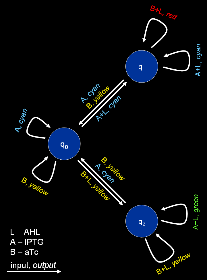
[[Image:FSM.png|thumb|350px|Figure 1: Graph representing the finite state machine.]] | [[Image:FSM.png|thumb|350px|Figure 1: Graph representing the finite state machine.]] | ||
The proposed system is best described by a [http://en.wikipedia.org/wiki/Mealy_machine Mealy machine], a special type of [http://en.wikipedia.org/wiki/Finite_state_machine finite state machines] (FSM). Mealy machines are defined by a 6-tuple, (''Q'', ''q''<sub>0</sub>, Σ, Λ, ''δ'', ''Ω''), with: | The proposed system is best described by a [http://en.wikipedia.org/wiki/Mealy_machine Mealy machine], a special type of [http://en.wikipedia.org/wiki/Finite_state_machine finite state machines] (FSM). Mealy machines are defined by a 6-tuple, (''Q'', ''q''<sub>0</sub>, Σ, Λ, ''δ'', ''Ω''), with: | ||
Revision as of 12:03, 18 October 2007
.:: Finite State Machine View on the System ::.
The proposed system is best described by a [http://en.wikipedia.org/wiki/Mealy_machine Mealy machine], a special type of [http://en.wikipedia.org/wiki/Finite_state_machine finite state machines] (FSM). Mealy machines are defined by a 6-tuple, (Q, q0, Σ, Λ, δ, Ω), with:
- Q - a set of states, for the proposed system we use three different states (q0 - not yet trained, q1 - trained to recognize chemical A, q2 - trained to recognize chemical B)
- q0 - a start state, here we assume we start in a state where the system is not yet trained
- Σ = {A+L, A, B+L, B} - an input alphabet
- Λ = {green, red, blue, yellow} - an output alphabet
- δ : Q × Σ → Q - a state transition function
- Ω : Q × Σ → Λ - an output function
In detail, the transition function δ and the output function Ω look as follows:
| inputs/states | q0 | q1 | q2 | inputs/states | q0 | q1 | q2 | |
|---|---|---|---|---|---|---|---|---|
| A+L | q1 | q1 | q1 | A+L | green | green | blue | |
| A | q0 | q0 | q0 | A | green | green | green | |
| B+L | q2 | q2 | q2 | B+L | yellow | red | yellow | |
| B | q0 | q0 | q0 | B | yellow | yellow | yellow |
The resulting automaton is shown in Fig. 1.
In its native state (q0), the system reacts on the presence of either chemical A or B by fluorescing green or yellow, respectively. The system itself remains in state q0. Only when the input chemical is combined with a learning signal (chemical L), it changes its state either to q1 (in presence of chemical A) or q2 (in presence of chemical B). In these two states, the system is able to distinguish between changing input: while the system is in state q1, the system starts fluorescing red if confronted with chemical B and vice versa when the system is in state q2 and confronted with chemical A (it fluoresces blue). In order to maintain the states q1 and q2, the learning signal L has to be present all the time.
