USTC/Introduction
From 2007.igem.org
m |
m |
||
| Line 5: | Line 5: | ||
==NOR Gate== | ==NOR Gate== | ||
[[Image:ustc_nor gate.jpg|thumb|256px]] | [[Image:ustc_nor gate.jpg|thumb|256px]] | ||
| - | [[Image: | + | [[Image:USTC_TruthTableNOR.png]] |
| Line 16: | Line 16: | ||
==NAND Gate== | ==NAND Gate== | ||
[[Image:ustc_nand gate.jpg|thumb|256px]] | [[Image:ustc_nand gate.jpg|thumb|256px]] | ||
| - | [[Image: | + | [[Image:USTC_TruthTableNAND.png]] |
The NAND operation is a logical operation on two logical values, typically the values of two propositions, that produces a value of false if and only if both of its operands are true. In other words, it produces a value of true if and only if at least one of its operands is false. A LOW output results only if both the inputs to the gate are HIGH. If one or both inputs are LOW, a HIGH output results.(from wikipedia) | The NAND operation is a logical operation on two logical values, typically the values of two propositions, that produces a value of false if and only if both of its operands are true. In other words, it produces a value of true if and only if at least one of its operands is false. A LOW output results only if both the inputs to the gate are HIGH. If one or both inputs are LOW, a HIGH output results.(from wikipedia) | ||
| Line 27: | Line 27: | ||
==NOT Gate== | ==NOT Gate== | ||
[[Image:ustc_not gate.jpg|thumb|256px]] | [[Image:ustc_not gate.jpg|thumb|256px]] | ||
| - | [[Image: | + | [[Image:USTC_TruthTableNOT.png]] |
The NOT gate is a digital logic gate that implements logical negation. It behaves according to the truth table to the left. A HIGH output (1) results if the inputs is LOW (0). If the input is HIGH (1), a LOW output (0) results. (from wikipedia) | The NOT gate is a digital logic gate that implements logical negation. It behaves according to the truth table to the left. A HIGH output (1) results if the inputs is LOW (0). If the input is HIGH (1), a LOW output (0) results. (from wikipedia) | ||
Revision as of 07:20, 21 October 2007
Logic Artificial Biological Circuit (ABC) and logic Integrated Circuit (IC) are both composed of "components" and "wires". Though people have been enjoying the advantages of Ultra Large Scale IC (ULSI), we still cannot implement in real experiments a somewhat large-scale logic ABC with several levels of logic gates in it.
Our project is to provide a new method for building up a fully extensible logic ABC. For some biological convenience, we are going to produce such biological logic gates as NAND, NOR, NOT which are exactly the basis for modern logic IC. More importantly, several factors influence the scale of ABC and IC, such as, the size and power of the components, the interference between wires, and standardization of intercommunication. Cis-acting components in ABC may present a smaller scale and power request than trans-acting ones, while the other two factors can be improved by novelly-designed and calibrated wires. We are also going to demonstrate an ABC made by these biological logic gates and wires.
NOR Gate
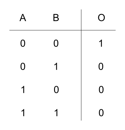
The NOR gate is a digital logic gate that implements logical NOR - it behaves according to the truth table to the left. A HIGH output (1) results if both the inputs to the gate are LOW (0). If one or both input is HIGH (1), a LOW output (0) results. In other words, it produces a value of false if and only if at least one operand is true. (from wikipedia)
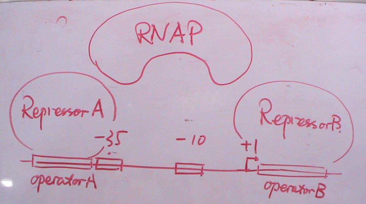
The draft to the right shows the NOR Gate we have determined ourselves to experimentally implement. It is an extract made from our weekly group meeting. As is shown in the draft, the RNA Polymerase cannot bind to the its target site.
<TODO>
NAND Gate
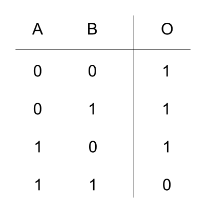
The NAND operation is a logical operation on two logical values, typically the values of two propositions, that produces a value of false if and only if both of its operands are true. In other words, it produces a value of true if and only if at least one of its operands is false. A LOW output results only if both the inputs to the gate are HIGH. If one or both inputs are LOW, a HIGH output results.(from wikipedia)
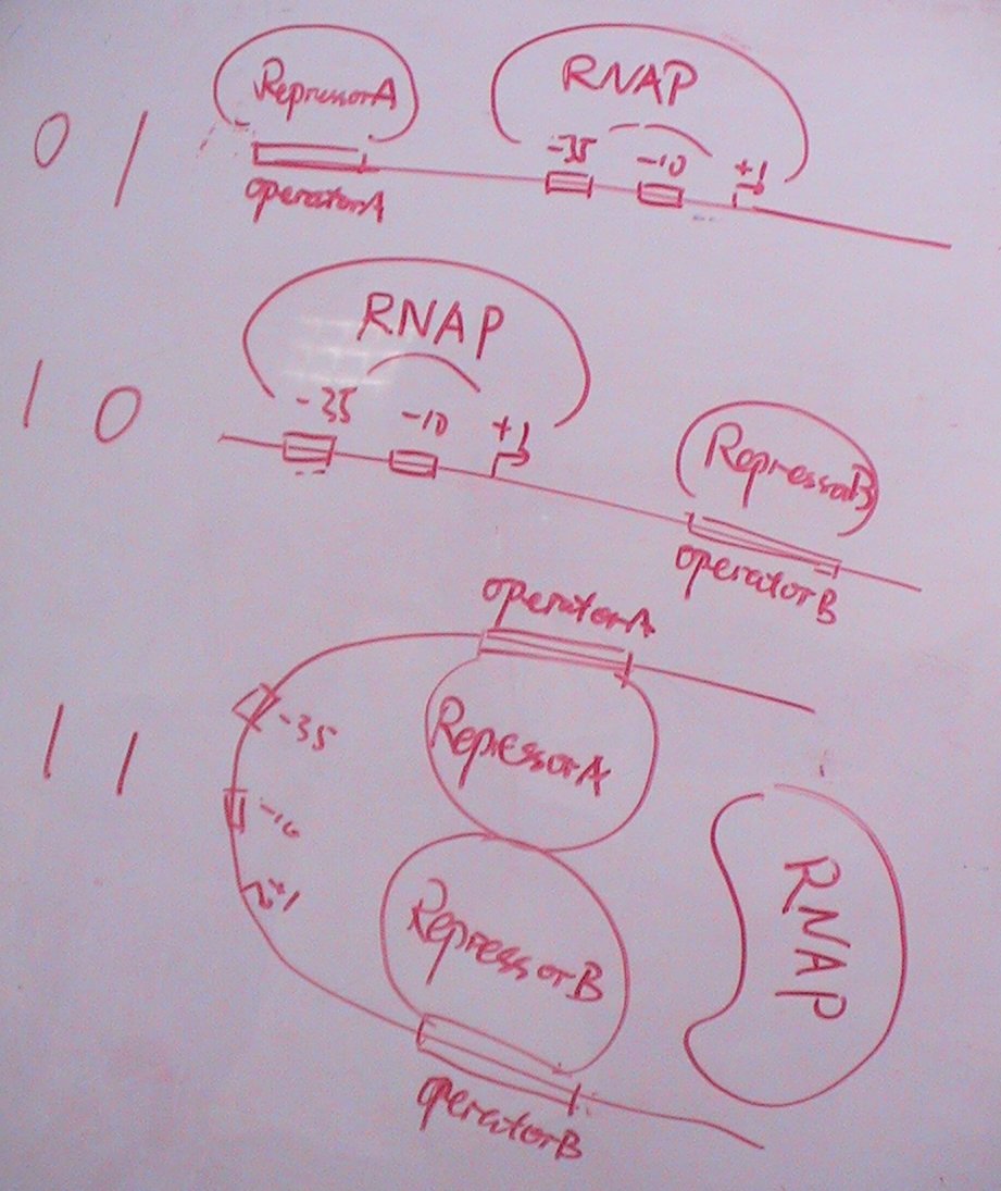
The draft to the right shows the NAND Gate we are destined to physically realize. It is also an extract made from an ordinary group meeting.
<TODO>
NOT Gate
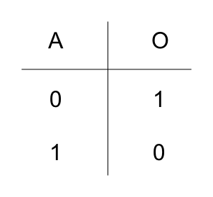
The NOT gate is a digital logic gate that implements logical negation. It behaves according to the truth table to the left. A HIGH output (1) results if the inputs is LOW (0). If the input is HIGH (1), a LOW output (0) results. (from wikipedia)
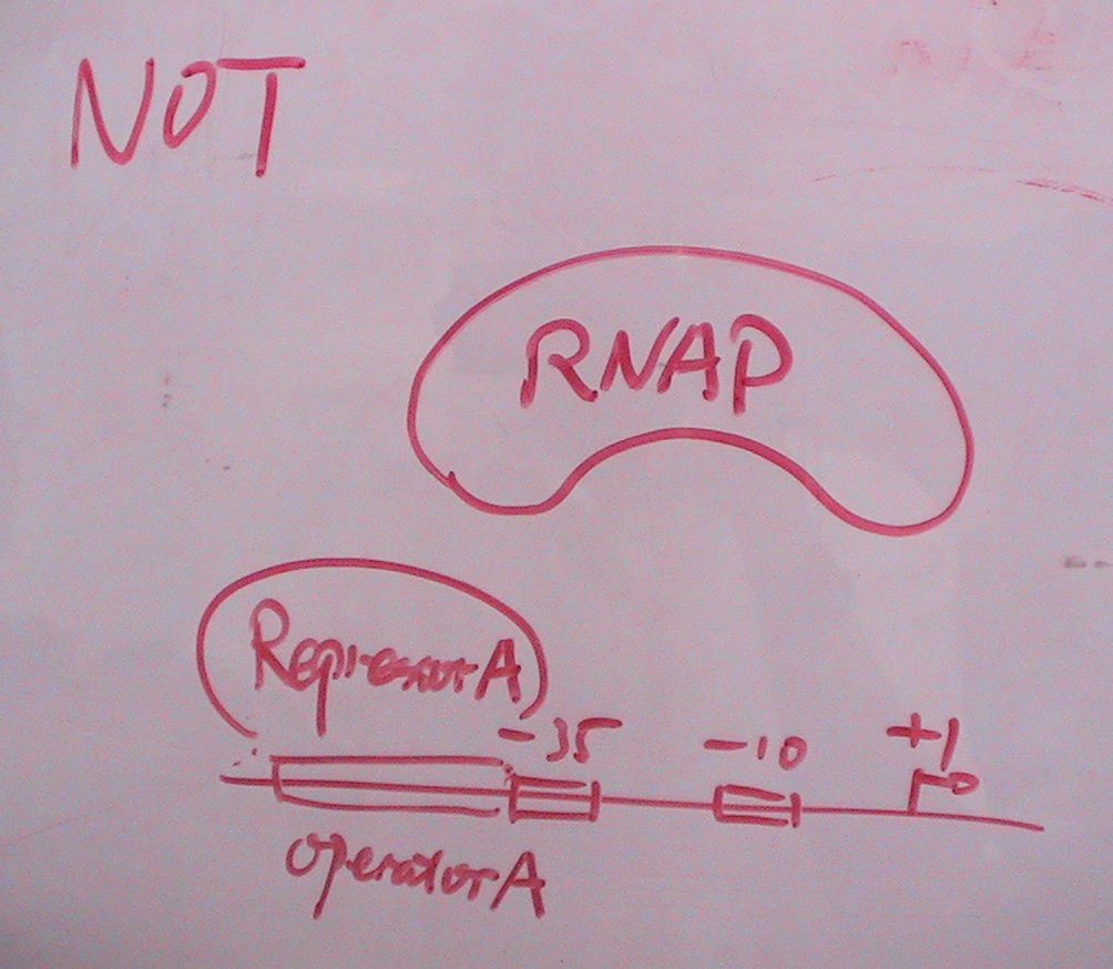
The draft to the right shows the NOT gate we plan to complete in the project.
The existence of repressor A fulfils the function of a simple NOT Gate. RNA Polymerase will not bind to the according RBS when the repressor has already bounds an operator. Not until the operator is relieved from the repressor will the RNA Polymerase come to work again.
