Imperial/Infector Detector/Modelling
From 2007.igem.org

Infector Detector: Modelling
Abstract
Infector Detector (ID) is a simple biological detector, which serves to expose bacterial biofilm. It functions by exploiting the inherent AHL (Acetyl Homoserine Lactone) production employed by certain types of quorum-sensing bacteria, in the formation of such structures.
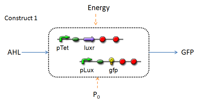
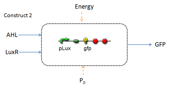
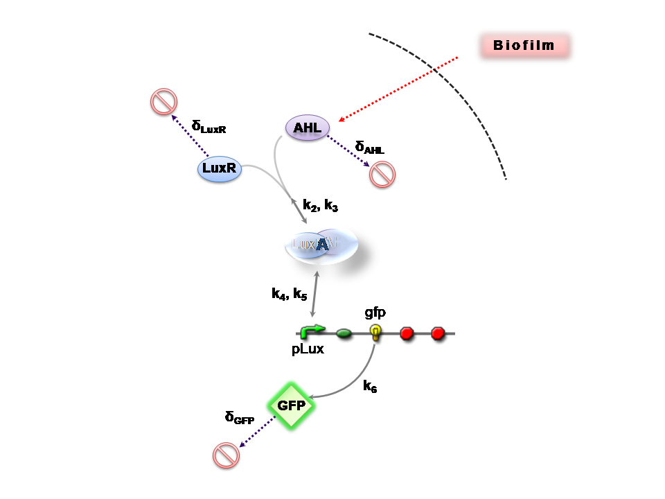
This section presents a preliminary model for an AHL detector, which employs the backbone of the Lux quorum-sensing feedback mechanism. Figures 1 and 2 below illustrate the full system we are investigating.
In the design phase, two possible system constructs were proposed, as a solution to the problem of detecting AHL-producing biofilm.
According to our specifications, the most crucial feature of this system is the sensitivity to a minimum [AHL] of 5nm. In other words, we need to identify the minimal AHL concentration for appreciable expression of a chosen reporter protein.
Furthermore, we attempt to define a functional range for possible AHL detection. How does increased AHL concentration impact on the maximal output of reporter protein?
Finally, we investigate how the system performance can be tailored, by exploiting possible inputs to the system (e.g. varying initial LuxR concentration and/or concentration of pLux promoters).
In performing such customizations, the question arises: what is the impact upon the maximal output of fluorescent reporter protein and/or response time?
We attempt to answer such questions by establishing a representative model, and consequently, conducting a simulation of the system in-silico.
Implementation & Reaction Network
Representative Model
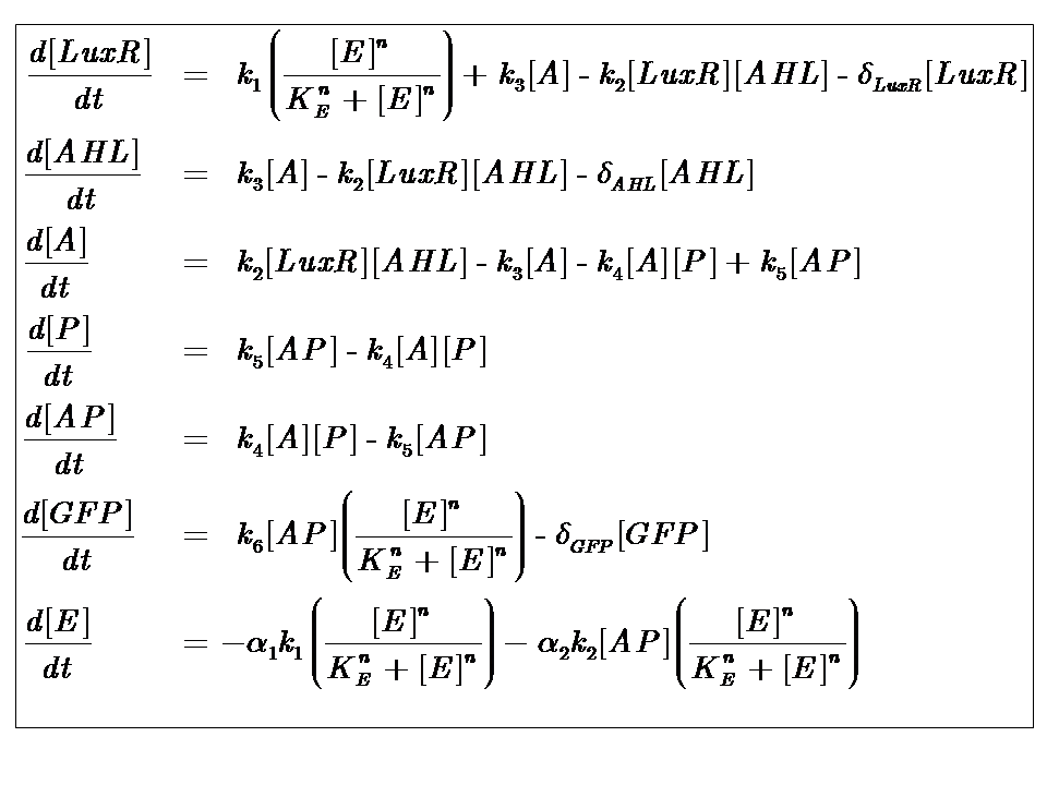
At reasonably high molecular concentrations of the state variables, a continuous model can be adopted, which is represented by a system of ordinary differential equations.
It is for this reason that our approach to modelling the system follows a deterministic, continuous approximation. In developing this model, we were interested in the behaviour at steady-state, that is when the system has equilibrated and the concentrations of the state variables remain constant.
We can condition the system in various manners, but for the purposes of our project, we will seek a formulation which is valid for both constructs considered, i.e. the governing equations are a represenation of both constructs.
The only difference is with regards to the parameter k1, the maximum transcription rate of the constitutive promoter (pTET) in Construct 1.
Thus k1 = 0 for construct 2 (which lacks pTET).
Our analysis took us through a number of models, but presented here is the most pertinent, most representative version. This model is based on energy-dependence (limited nutrient supply), which follows Hill-like dynamics.
The system kinetics are determined by the following coupled-ODEs. For a derivation of the governing equations, please access
Model Parameters
| Parameter | Description |
|---|---|
| Kinetic Constants | |
| k1 | Maximal constitutive transcription of LuxR by pTET |
| k2 | Binding between LuxR and AHL |
| k3 | Dissociation of protein complex LuxR-AHL (A) |
| k4 | Binding between A and pLux promoter |
| k5 | Dissociaton of A-pLux complex |
| k6 | Transcription of FP |
| Degradation Rates | |
| δLuxR | Degradation rate of LuxR |
| δAHL | Degradation rate of AHL |
| δGFP | Degradation rate of GFP |
| Hill Co-operativity | |
| n | Co-operativity coefficient describing the degree of energy dependence, which follows Hill-like dynamics |
| Energy consumption of transcription | |
| α1 | Energy consumption due to constitutive transcription of LuxR |
| α2 | Energy consumption due to transcription of gfp gene |
We now present the essential features of the system behaviour, simulated for a given set of parameters.
Simulations
Jaroslaw - Should we create a separate simulations page, perhaps? These plots are essential, and was also thinking of putting some 3-d plots of transfer function for C1 and C2. Also, this would allow more freedom with sizing of the images - better clarity if greater. I really don't think these simulations need to be cramped here.
Presented below are the most essential features of the simulation performed.
Discussion
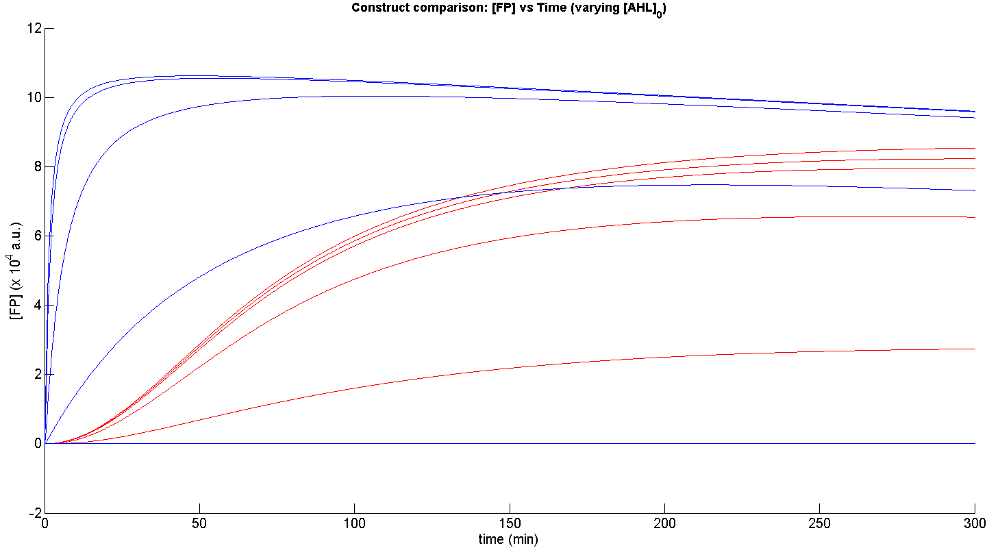
From figure 3, it is evident that the response time of construct 1 (C1) is far greater than that of construct 2 (C2). C1 crosses some arbitrary threshold, say 6000 a.u. at approximately t = 150min, whereas C2 below 10min. This is in line with our hypothesis, as we know steady-state has been forced upon the system in the case of construct 2 - by flooding the system with purified LuxR.
Secondly, the peak expression (max output) of GFP obtained for C1 is lower by approximately 50 percent. So, C2 produces a stronger output for corresponding [AHL]. However, although C2 is faster and generates a greater output, its energy consumption is far more pronounced. C1 thus has a greater lifespan.
Finally, in terms of sensitivity, construct 2 is also more sensitive to lower [AHL]; for the lowest [AHL] simulated, the peak output is 3 times greater than that of construct 1.
Discussion
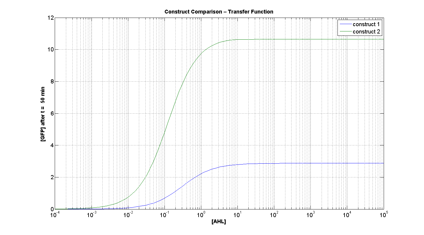
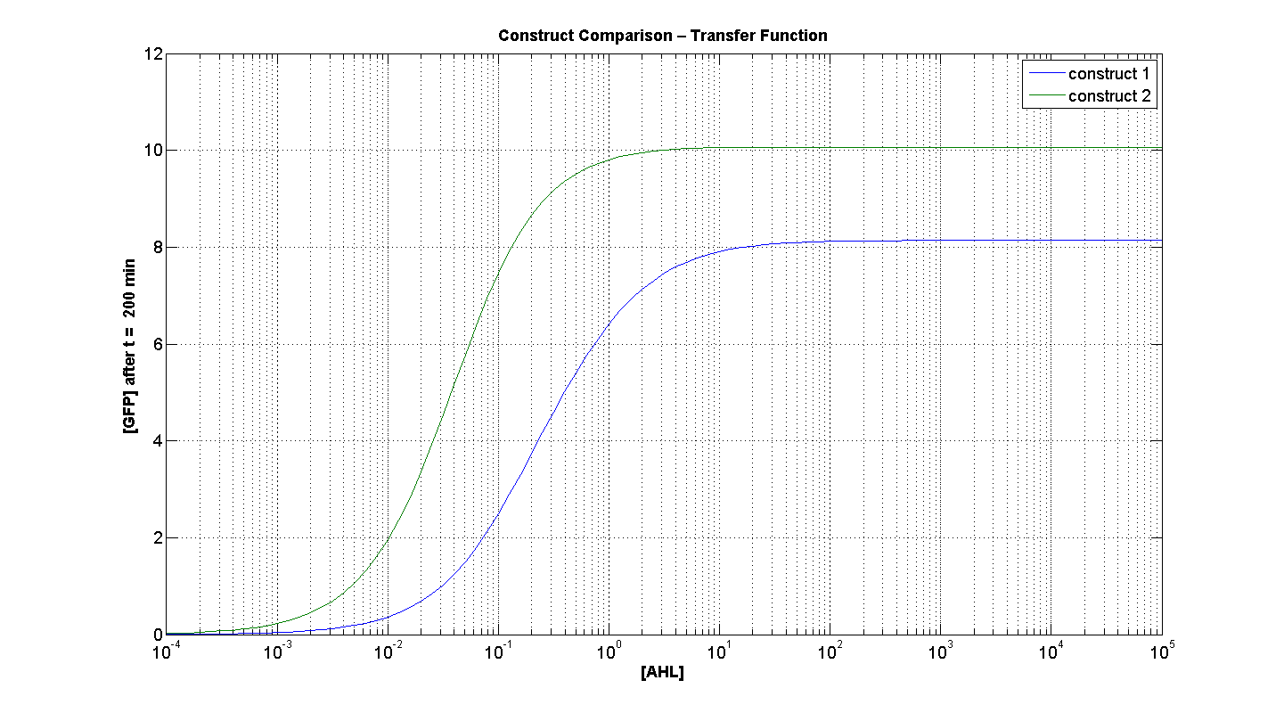
Figures 4 and 5 illustrate the comparison of the transfer function of both constructs, at two time instances: t = 50min and t = 200min. Consider figure 5, which illustrates the greater sensitivity to AHL offered by construct 2. Appreciable expression of GFP occurs at concentration of AHL at least one order of magnitude lower than in the case of construct 1.
It can also be seen, that at saturation, the peak expression, is considerably greater - approximately 25 % greater than the max output generated by C1. Obviously, figure 4, portrays, the far superior response time of C2 (as expected).
