USTC/Inputs and Outputs
From 2007.igem.org
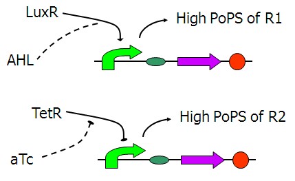
PoPS (the flow of RNA Polymerase molecules along DNA) means the current of gene expression. Our logic gates accept PoPS input signals, but we cannot input a PoPS signal directly. We decide to add something into our system as input signal, such as cheminal ligands and light. So a convertor must be built firstly to convert these signals to PoPS signals.
Contents |
Candidates of input signals
Light
We decide not to use light signals as the inputs of our system for the following two reasons.
For one, it would be rather difficult to dynamically control the light intensity in real experiments. Compared with simply adding reagents to the solutions, controlling the input level of light is far more complicated. Still unpleasant is the requirement for the techniques of keeping the light sensors on the cell membrane from frequent exposure.
For another, since light has seldom been applied as input signals before, there is little relative background knowledge and experience to us.
IPTG
IPTG is actually the RESET signal of the whole system. Once added, it will let all the repressor-operator pairs in the system lose their function. All the outputs will consequently become 1 with all the inputs automatically being ignored.
aTc
ATC the substance is a well studied and widely used inducer of celluar communication. We take a fancy to its stable properties and reasonable price.
AHL
Arabinose
Design of PoPS converters
The figure above shows the basic structure of our input device. It functions to convert chemical signals to the PoPS (the flow of RNA Polymerase molecules along DNA) signals of lac repressor and CI, which are actually the wires of our system.
PoPS-converter parts
Figure 2 is our first design of the [aTc]->PoPS converters. Fluorescent reporters was added behind it, and it is found that the background expression cannot be ignored under fluorescent microscope. It may be caused by the LVA tag of Tet repressor which makes the repressor weak. So we decide to remove the LVA tag of Tet repressor like the one showed in Figure 3.


