USTC/Inputs and Outputs
From 2007.igem.org
Contents |
Input Devices
PoPS (the flow of RNA Polymerase molecules along DNA) means the current of gene expression. Our logic gates accept PoPS input signals, but we cannot input a PoPS signal directly. We decide to add something into our system as input signal, such as cheminal ligands and light. So a convertor must be built firstly to convert these signals to PoPS signals.
Candidates of input signals
Light
We decide not to use light signals as the inputs of our system for the following two reasons.
For one, it would be rather difficult to dynamically control the light intensity in real experiments. Compared with simply adding reagents to the solutions, controlling the input level of light is far more complicated. Still unpleasant is the requirement for the techniques of keeping the light sensors on the cell membrane from frequent exposure.
For another, since light has seldom been applied as input signals before, there is little relative background knowledge and experience to help us.
IPTG
IPTG is actually the RESET signal of our whole system. Once added, it will let all the repressor-operator pairs in the system no longer function. All the outputs will consequently become 1 as well as all the input repressing signals being automatically ignored. (It just likes the "8888..." on the screen when you reset your calculator or some other digital equipment.)
aTc
ATC is a well studied and widely used inducer of cellular communication. We take a fancy to its stable properties and reasonable price. Certainly, there are still some problems, for example, aTc at a high concentration shows some bacteriostatic activity like Tc(TetraCycline). Unfortunately we have to use concentrated aTc for counteracting the high expression of TetR repressor protein.
AHL
We consider AHL a well-qualified input signal that is normally used in quorum sensing. Actually, we choose 3OC6HSL, a member of AHL family to be the input signal, and its according receptor LuxR to be the sensor. Here we find it no problem to use dilute AHL although LuxR is also high expressing, because LuxR is activator and AHL is its accelerator.
Arabinose
Considering that the promoter of arabinose requires to match and is too much limited by the genotype of the host strain, we finally give up the idea that arabinose would serve as an input signal.
Design of PoPS converters
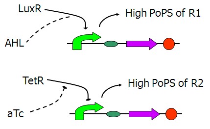
The figure above shows the basic structure of our input device. It functions to convert the input chemical signals to the PoPS (the flow of RNA Polymerase molecules along DNA) signals of the lac repressor A and B, the wires that will actually connect the two main parts of our system together.
PoPS-converter parts
Figure 2 is the first design of our [aTc]->PoPS converter. Fluorescent reporters was added behind. However, we found that the background expression could not be ignored under the fluorescent microscope. It might be due to the LVA tag of Tet repressor which served to help TetR degrade. Therefore, we decide to remove the LVA tag of the Tet repressor like the one shown in Figure 3.
We take [http://partsregistry.org/Part:BBa_J09855 BBa_J09855] directly from the registry as [AHL]->PoPS converter. Fluorescent expression under different [3OC6HSL] has been tested and the results show that this part is a perfect input device in this study.
Output Devices
For convenience reason, we choose LacZ and fluorescent proteins as corresponding quanlitive and quantitative reporters. With LacZ, we can roughly estimate the property of a gate candidate while with fluorescent proteins, we can further examine those candidates that pass the LacZ test under fluorescent microscopy, then pick out the better one.
Fluorescent Proteins
Red Fluorescent Protein (RFP) and Green Fluorescent Protein (GFP) are used in our systems as reporters. In most of the measurements, we use the stable version ([http://partsregistry.org/Part:BBa_E0040 BBa_E0040] and [http://partsregistry.org/Part:BBa_E1010 BBa_E1010]). But these fluorescent proteins are too stable for fast kinetics. So the unstable version with LVA tag have also been synthesized ([http://partsregistry.org/Part:BBa_I732077 BBa_I732077] and [http://partsregistry.org/Part:BBa_I732078 BBa_I732078]) to reduce the half life. However, the untagged fluorescent proteins could better match our expectation, so that we construct the final version of reporter system with the stable RFP and GFP.
LacZ: Beta-Galactosidase Activity
LacZ is widely used as qualitative reporter. The full-length LacZ gene ([http://partsregistry.org/Part:BBa_I732005 I732005]) is too long to be operated in molecular cloning. So we usually use a short fragment of the full-length LacZ gene called LacZ α-fragment ([http://partsregistry.org/Part:BBa_I732006 I732006]) as a substitute of the full-length gene(the beta-galactosidase activity can be restored by the rest of LacZ gene in the chromosomal DNA). The beta-galactosidase activity produced by lacZ gene can be observed on X-gal plates by naked eyes, and can also be quantitatively measured using ONPG Assay.
Double Reporter System
To combine the advantages of the mentioned two reporter, we construct a double reporter system consisting of both LacZ and fluorescent protein. The following figures show the 3 versions of the system(refer to BBa_I732091,BBa_I732092,BBa_I732093) and version 3, the untagged stable GFP, is our final choice.


