USTC/Further More
From 2007.igem.org
Contents |
Further Optimization
Though the existing bio-logic gates and wires are able to form a practicable combinational logic circuit in a bacterial cell, there remain some bottlenecks limiting the capability of our method.
- Size of the Wires
The size of wires are much larger than the gates in our system. We think it should be reduced. Some ligands, for example, peptides, saccharides, lipid and so on, might be used as signal carrier.
- More Input Signals
More signals with high quality are needed in larger-scale bio-logic circuit to serve as inputs. We think computational protein-ligand design can play an important role in providing more highly-specificied protein-ligand pairs.
- Response Time
At present, the response time of our bio-logic gates is much longer than that of electronic ones. This situation should be improved.
- I/O Standardization
Intensity of the input and output signals for different gates should be adjusted to the same level. There are several proposals as following.
Conductance Adjusting
As mentioned above, the non-interference Repressor/Operator pairs can function well as “wires”. Of course, different pairs have different strength of bond. Binding intensity may also be different even if the two components are of the same type. Therefore, these wires will transmit different intensity of signals from upstream components to downstream ones. In qualitative or semiquantitative experiments, this will not be a serious problem, but we must solve it for experiments that are more precise.
We all know that different promoters can initiate transcription strongly or weakly ([http://partsregistry.org/Part:BBa_J23100 Parts:BBa_J23100 and its family]). On the other hand, various RBS may lead to various efficiency of translation ([http://partsregistry.org/Part:BBa_J61100 Parts:BBa_J61100 and its family] and [http://partsregistry.org/JCA_Arkin_RBSFamilyPart2 JCA_Arkin_RBS Family]). Naturally, we will think of the following two approaches: using different promoters or using different RBS. However, according to the idea of “modularization”, we don’t want to casually modify promoters because these promoters are the kernel elements of our logic components. Anyway, we can modify other elements around this kernel, i.e. the RBS and operators. Let’s imagine the wires--every wire has two ends, and each of our Repressor/Operator pairs is a monodirectional wire. The beginning end is the RBS that activates the translation of this repressor protein, and the tail end is the operator to which an according repressor can bind.
To modify the RBS or operators is just like changing the conductance at the junctions of actual wires, so we call it “Conductance Adjusting”:
Using different RBS
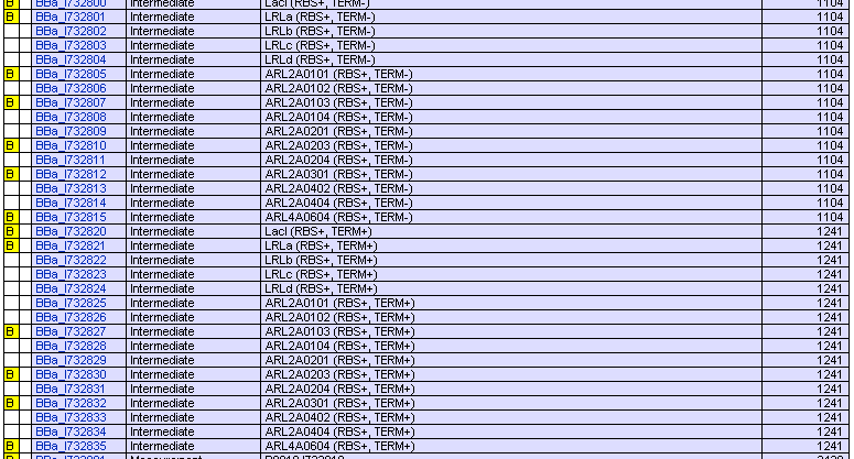
Registry of Standard Biological Parts have provided many kinds of RBS whose activities varies in a wide range ([http://partsregistry.org/Part:BBa_J61100 Parts:BBa_J61100 and its family] and [http://partsregistry.org/JCA_Arkin_RBSFamilyPart2 JCA_Arkin_RBS Family]). We’ve submitted our repressor protein coding parts without RBS or terminator so that every one can assemble them with appropriate RBS to get any efficiency of translation he wants.
We have also submitted those protein coding parts with RBS B0034 and terminator B0015 assembled. If you care nothing for the difference between different RBS, well, then they are good enough.
Using different Operators
TODO by Ma Rui

