Glasgow/Goals/FuelCells
From 2007.igem.org
 | Back To Glasgow's Main Page | Back To Glasgow's Project Page |
|---|
Microbial Fuel Cells
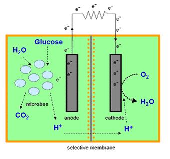
Most microbial cells are electrochemically inactive. The electron transfer from microbial cells to the electrode is facilitated by mediators such as thionine, methyl viologen (methyl blue), neutral red etc, and of the mediators available are expensive and toxic. Microbial fuel cells produce power by use of a microbial cell-permeable chemical mediator, which in the oxidised form intercepts a proportion of NADH (nicotinamide adenine dinucleotide) within the microbial cell and oxidises it to NAD+. The now reduced form of mediator is also cell-permeable and diffuses away from the microbial cell to the anode where, the reduced redox mediator is then electro-catalytically re-oxidised. In addition, cell metabolism produces protons in the anodic chamber, which may migrate through a proton selective membrane to the cathodic chamber. In the latter, they are consumed by ferricyanide (Fe3-(CN)6) and incoming electrons (via the external circuit) reducing it to ferrocyanide (Fe4-(CN)6 ). The oxidised mediator is then free to repeat the cycle. This cycling continually drains off metabolic reducing power from the microbial cells to give electrical power at the electrodes. Our mediator is pyocyanin and this has been shown to improve performance of fuel cells (Rabaey et al, 2003).
Our Own Microbial Fuel Cells
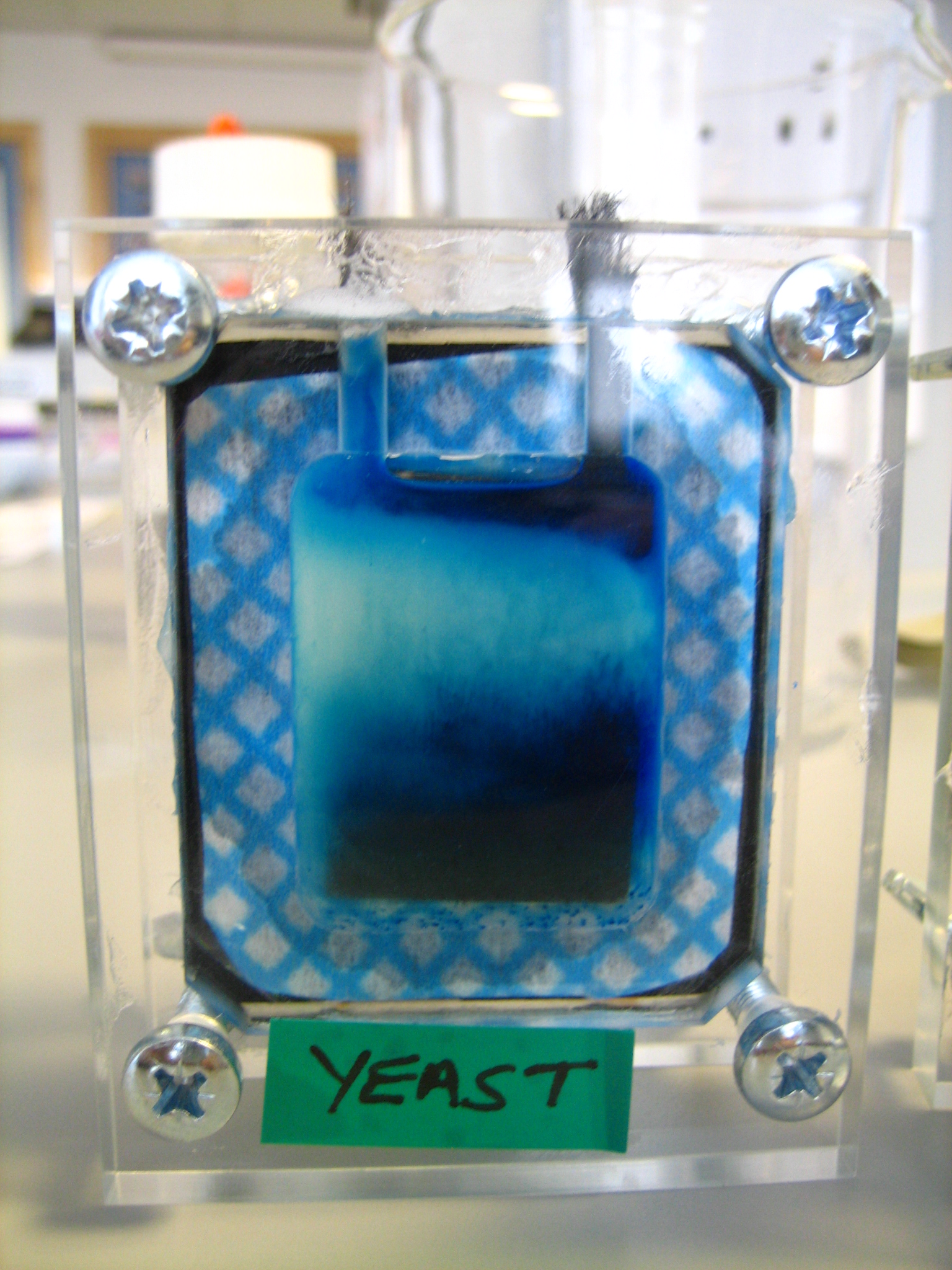
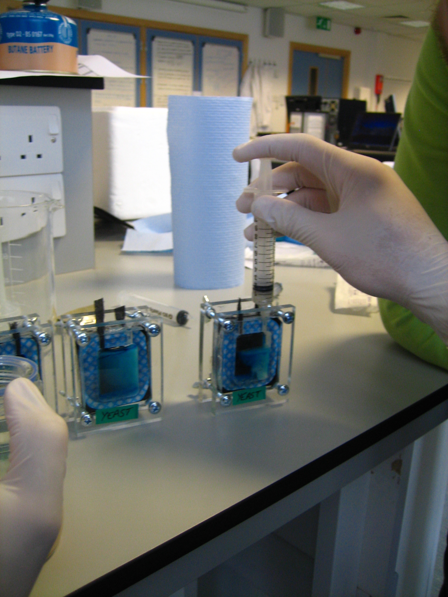
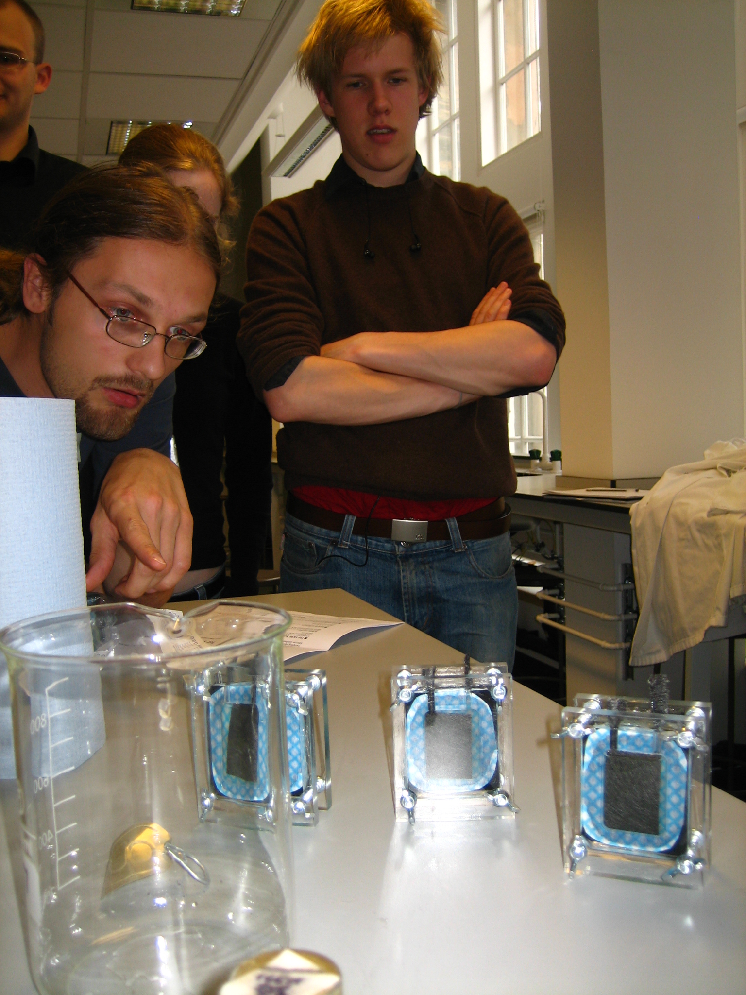
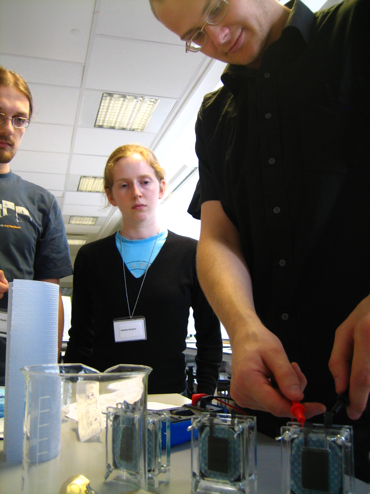
We decided to give microbial fuels cells a go ourselves. Starting with yeast as our organism, glucose as our energy source and methlylene blue as our mediator. The kits we used were ordered from the University of Reading. This is the initial recipe we followed:
Into one side of the cell inject 10 ml hexacyanoferrate (III) solution (in phosphate buffer). Into the other side inject 3.3 ml yeast slurry, 3.3 ml methylene blue solution, and 3 ml glucose solution. Each side of the cell holds 10 ml. Make sure they are tight and sealed (can use vasceline) because they are prone to leakage. Electrodes work best if the carbon fibre is rolled at the outer extremity.
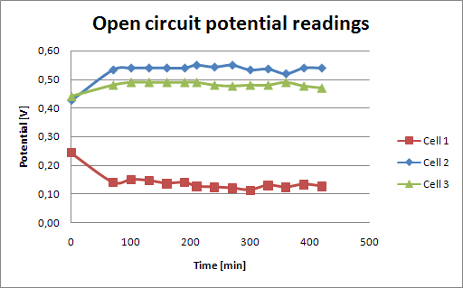
Comparison of open circuit readings
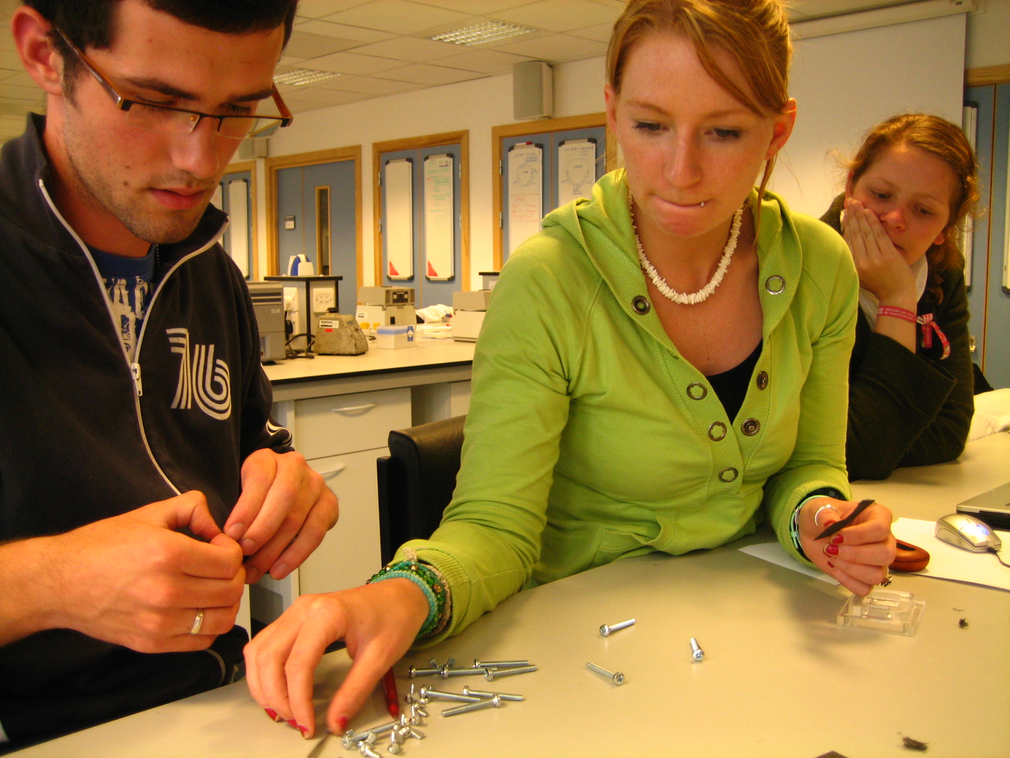
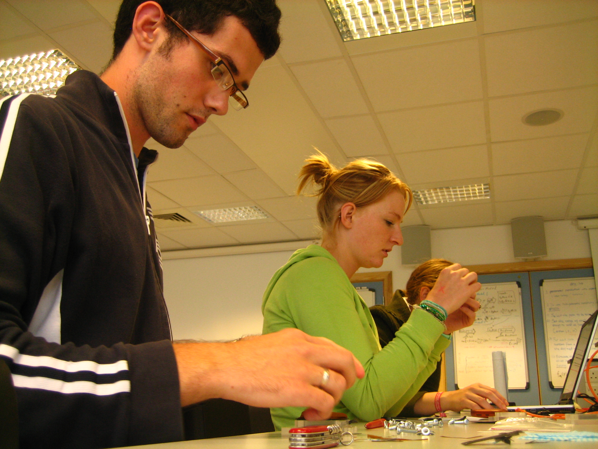
Fuel Cell Assembly
| 
| 
|
| 
| 
|
