Valencia/Electronic comparator
From 2007.igem.org


|
|
The basis of our biological comparator, is the digital comparator. All our project, consist in transform the system of an electronic comparator in a biological process which behavior must represent the function of a comparator. With the aim to understand how our biological comparator should be, first we must study how an electronic comparator works.
The comparator function
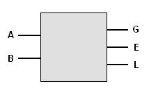
To start with we must know how it's going to work. We must work with binary because its an electronic device, and its inputs and outputs will be 0 or 1. In our case, 0 and 1 represents False and True. Let be the inputs A and B, and the outputs G, E and L, for Greater, Equal, and Less.
The comparator works like this:
- If A > B, (A is grater than B),we get G=1, and 0 at E and L.
- If A = B, (A equal to B), E=1 and the rest 0.
- If A < B, (A less than B), L=1 and the rest 0
Is usually represent these conditions in a Truth Table
| A | B | G | E | L |
| 0 | 0 | 0 | 1 | 0 |
| 1 | 0 | 1 | 0 | 0 |
| 0 | 1 | 0 | 0 | 1 |
| 1 | 1 | 0 | 1 | 0 |
So, we can construct the mathematical conditions to find the proper logic gates and construct our device.
- G is True when A>B. A=1, B=0
- G=A·B'
- E is True when A=B. Two cases A=B=0 or A=B=1.
- E=A'·B'+A·B
- L is True when A<B. A=0, B=1
- L=A'·B
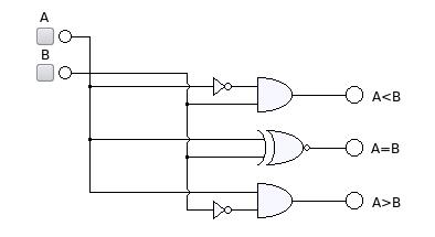
We suppose known the equivalences between the mathematical operators and the logic gates. The (') is the gate NOT, which switch 1 and 0; the operation (·) is the AND gate; and the equation for E, is the formula for the XNOR gate. So is easy construct the electronic diagram with this information.


