Imperial/Wet Lab/Results/ID3.1
From 2007.igem.org
m (→Discussion) |
m (→Discussion) |
||
| Line 39: | Line 39: | ||
The idea behind using molecules of GFPmut3b is to try to standardise our units for the chassis and normalise our data based upon the number of DNA plasmids present in our system. This idea is similar to that for the F2620 which uses the units GFP molecules synthesized per second per cell. Trying to normalise this data with the plasmids helps to make our data independent of the DNA used in this assay, i.e. for other constructs tested and characterized in vitro. | The idea behind using molecules of GFPmut3b is to try to standardise our units for the chassis and normalise our data based upon the number of DNA plasmids present in our system. This idea is similar to that for the F2620 which uses the units GFP molecules synthesized per second per cell. Trying to normalise this data with the plasmids helps to make our data independent of the DNA used in this assay, i.e. for other constructs tested and characterized in vitro. | ||
| - | + | Figure 1.1 shows; | |
| - | + | *Functional at 25<sup>o</sup>C | |
| - | The | + | *The output of '''GFPmut3b increases with input of AHL''' |
| - | + | *The system is sensitive to a range of '''5-1000nM AHL''' | |
| - | The | + | *The GFPmut3b molecules synthesis stops at '''~300minutes'''. This could be due to steady state or due to no synthesis of GFPmut3b. It is known not to be steady state because the [[Imperial/Wet_Lab/Results/Res1.4| degradation experiment]] proved degradation is negligible. Interestingly this time at which synthesis stops is independent of the GFPmut3b molecules produced as all the [AHL] level off at the same time. This shows that the LuxR under the control of pTet is the major source of energy consumption. The pTet is a very strong promoter and is a big consumer of the energy of the chassis. This highlights the advantages of using the construct 2 [http://partsregistry.org/Part:BBa_J37032 pLux-GFPmut3b] that does not have the energetic burden of producing LuxR under pTet. <br><br> |
| + | Figure 1.2 shows us the following: | ||
| + | *The shape of the '''Transfer function''' shows a linear range of response between 5nM and 100nM AHL. This defines the thresholds of response. | ||
| + | *The '''lower threshold of response''' is the AHL concentration that the construct will respond | ||
| + | *The '''upper threshold of response''' is the value of AHL the system is saturated and increasing AHL will not increase the rate of GFP synthesis.<br><br> | ||
==Conclusion== | ==Conclusion== | ||
Revision as of 01:36, 27 October 2007

In vitro Testing of pTet-LuxR-pLux-GFPmut3b Construct with varying concentrations of AHL
Aims
To characterise the [http://partsregistry.org/Part:BBa_T9002 pTet-LuxR-pLux-GFPmut3b] construct in vitro. The characterisation is based upon giving inputs of varying AHL concentration and measuring the fluorescent output.
Materials and Methods
Link to the Protocols
Results
Controls:
- Negative Control- pTet-LuxR-pLux-GFPmut3b with no AHL
- Negative Control.2.- pLux with 1000nM AHL
Constants:
- Temperature - 25°C
- Volume - 60ul
- Sampling on same plate and every 30 minutes
Raw Data
File:AHL testing Final1.xls
Discussion
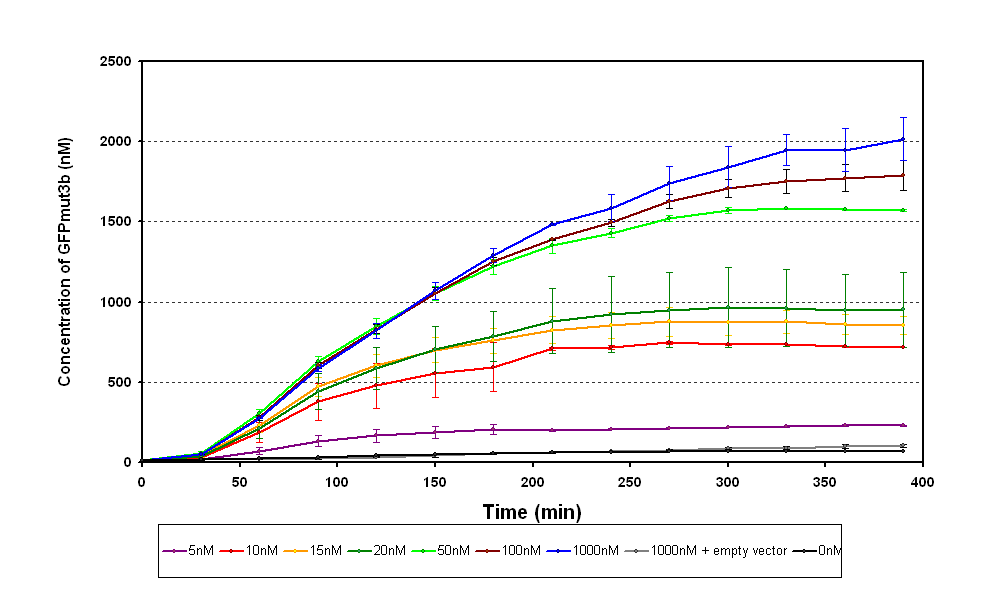
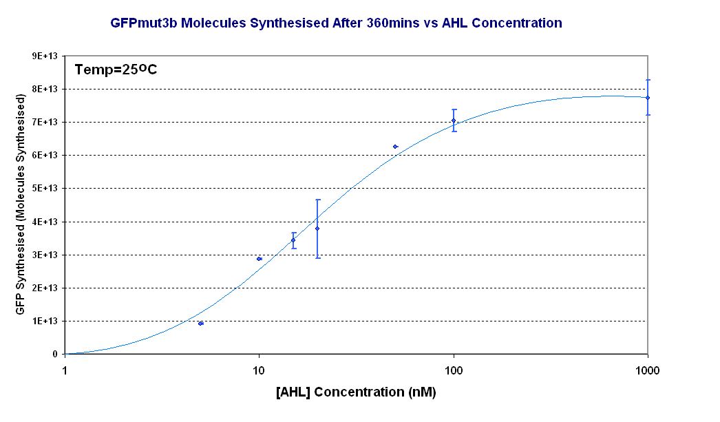
The results from the experiment were of fluorescence against time for varying levels of AHL. Using our calibration curves we managed to convert the fluorescence into concentration of GFPmut3b produced (figure 1.1) and also into Molecules of GFPmut3b synthesised per plasmid (figure 1.2). See the how the calibration curves allowed us to do this by following this link to converting units.
The idea behind using molecules of GFPmut3b is to try to standardise our units for the chassis and normalise our data based upon the number of DNA plasmids present in our system. This idea is similar to that for the F2620 which uses the units GFP molecules synthesized per second per cell. Trying to normalise this data with the plasmids helps to make our data independent of the DNA used in this assay, i.e. for other constructs tested and characterized in vitro.
Figure 1.1 shows;
- Functional at 25oC
- The output of GFPmut3b increases with input of AHL
- The system is sensitive to a range of 5-1000nM AHL
- The GFPmut3b molecules synthesis stops at ~300minutes. This could be due to steady state or due to no synthesis of GFPmut3b. It is known not to be steady state because the degradation experiment proved degradation is negligible. Interestingly this time at which synthesis stops is independent of the GFPmut3b molecules produced as all the [AHL] level off at the same time. This shows that the LuxR under the control of pTet is the major source of energy consumption. The pTet is a very strong promoter and is a big consumer of the energy of the chassis. This highlights the advantages of using the construct 2 [http://partsregistry.org/Part:BBa_J37032 pLux-GFPmut3b] that does not have the energetic burden of producing LuxR under pTet.
Figure 1.2 shows us the following:
- The shape of the Transfer function shows a linear range of response between 5nM and 100nM AHL. This defines the thresholds of response.
- The lower threshold of response is the AHL concentration that the construct will respond
- The upper threshold of response is the value of AHL the system is saturated and increasing AHL will not increase the rate of GFP synthesis.
Conclusion
These are the characteristics we have extracted
Switch Point= ~20nM AHL
Response Time= <30 minutes
Sensitivity = <5nM AHL
In terms of the specification of the Infector Detector Application the chassis and construct is sensitive enough.

