Imperial/Wet Lab/Results/ID1.7
From 2007.igem.org
m |
(→Discussion) |
||
| (5 intermediate revisions not shown) | |||
| Line 1: | Line 1: | ||
| + | {{Template: IC07navmenu}} | ||
| + | <br clear="all"> | ||
| + | __NOTOC__ | ||
| + | |||
= Testing of Purified LuxR ''In vitro''= | = Testing of Purified LuxR ''In vitro''= | ||
| - | |||
==Aims== | ==Aims== | ||
To determine if the purified LuxR is functional ''in vitro''. | To determine if the purified LuxR is functional ''in vitro''. | ||
| Line 9: | Line 12: | ||
Link to the [[Imperial/Wet_Lab/Protocols/Prot1.7|Protocols]] | Link to the [[Imperial/Wet_Lab/Protocols/Prot1.7|Protocols]] | ||
| - | '''Summary of the experiments''' | + | '''Summary of the experiments'''<br> |
We had two experiments to test the purified LuxR | We had two experiments to test the purified LuxR | ||
| - | *Test Purified LuxR with the [http://partsregistry.org/Part:BBa_T9002 '''pTet-LuxR-pLux-GFPmut3b''']. The modeling tells us that the system should respond quicker because there is no lag time for LuxR to be synthesised | + | *Test Purified LuxR with the [http://partsregistry.org/Part:BBa_T9002 '''pTet-LuxR-pLux-GFPmut3b''']. The modeling tells us that the system should respond quicker because there is no lag time for LuxR to be synthesised. |
*Test purified LuxR with [http://partsregistry.org/Part:BBa_J37032 '''pLux-GFPmut3b'''] | *Test purified LuxR with [http://partsregistry.org/Part:BBa_J37032 '''pLux-GFPmut3b'''] | ||
| Line 38: | Line 41: | ||
==Discussion== | ==Discussion== | ||
| - | Figure 1.1 shows two samples where purified LuxR was added to the ''in vitro'' chassis and one control sample where no LuxR was added. The samples | + | Figure 1.1 shows two samples where purified LuxR was added to the ''in vitro'' chassis and one control sample where no LuxR was added. The samples where LuxR was added had massive variation which makes comparison to the control sample difficult. However, the modelling suggests that if LuxR is functional there should be a quicker response at the start as there is no initial lag phase from pTet synthesizing LuxR. Our samples do not show a clear difference in the initial rate of response. Therefore the LuxR does not appear to have an affect on the response of the ''in vitro'' chassis. |
| - | Figure 1.2. shows various concentrations of LuxR added ''in vitro'' to the '''pLux-GFPmut3b''' construct. It can be seen that 100mM appears to be optimum above which the synthesis of GFPmut3b decreases. The | + | Figure 1.2. shows various concentrations of LuxR added ''in vitro'' to the '''pLux-GFPmut3b''' construct. It can be seen that 100mM appears to be optimum above which the synthesis of GFPmut3b decreases. The modelling of this experiment told us that the optimum value for LuxR should be around 100nM, this means the experiment agrees with the model. |
| - | When the molecules of GFPmut3b is compared to the figure 1.1 it can be seen that for the optimum [LuxR] the total output of GFPmut3b is less than half of the max of | + | When the molecules of GFPmut3b is compared to the figure 1.1 it can be seen that for the optimum [LuxR] the total output of GFPmut3b is less than half of the max of figure 1.1. The reason for this low output is thought to be due to the instability of purified LuxR protein. When the LuxR was purified it was noticed that the protein began to slowly precipitate. If the LuxR was instable or misfolded then -its function would be severly reduced. This helps to explain why the total output of GFPmut3b was so low because out of the 100nM of LuxR we are adding, only a small fraction was functional. |
==Conclusion== | ==Conclusion== | ||
Latest revision as of 03:20, 27 October 2007

Testing of Purified LuxR In vitro
Aims
To determine if the purified LuxR is functional in vitro.
Materials and Methods
Link to the Protocols
Summary of the experiments
We had two experiments to test the purified LuxR
- Test Purified LuxR with the [http://partsregistry.org/Part:BBa_T9002 pTet-LuxR-pLux-GFPmut3b]. The modeling tells us that the system should respond quicker because there is no lag time for LuxR to be synthesised.
- Test purified LuxR with [http://partsregistry.org/Part:BBa_J37032 pLux-GFPmut3b]
Results
Controls:
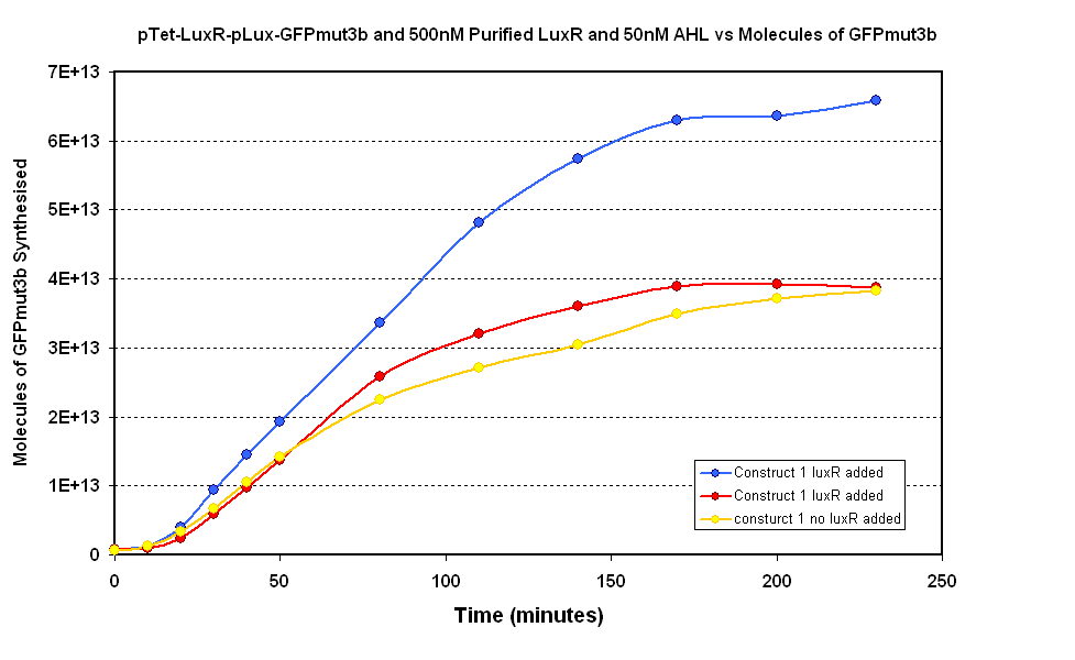
- Fig 1.1 Negative Control- pTet-LuxR-pLux-GFPmut3b with no purified LuxR
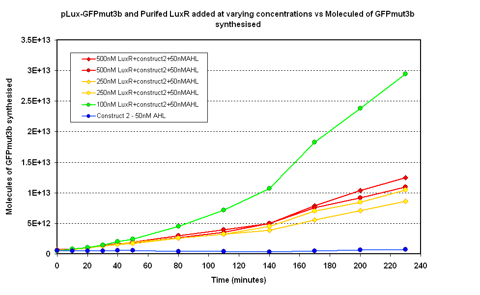
- Fig 1.2 Negative Control- pLux-GFPmut3b with no purified LuxR
Constants:
- Temperature - 25°C
- Total Volume - 60µl
- AHL added - 50nM
Raw Data
Discussion
Figure 1.1 shows two samples where purified LuxR was added to the in vitro chassis and one control sample where no LuxR was added. The samples where LuxR was added had massive variation which makes comparison to the control sample difficult. However, the modelling suggests that if LuxR is functional there should be a quicker response at the start as there is no initial lag phase from pTet synthesizing LuxR. Our samples do not show a clear difference in the initial rate of response. Therefore the LuxR does not appear to have an affect on the response of the in vitro chassis.
Figure 1.2. shows various concentrations of LuxR added in vitro to the pLux-GFPmut3b construct. It can be seen that 100mM appears to be optimum above which the synthesis of GFPmut3b decreases. The modelling of this experiment told us that the optimum value for LuxR should be around 100nM, this means the experiment agrees with the model. When the molecules of GFPmut3b is compared to the figure 1.1 it can be seen that for the optimum [LuxR] the total output of GFPmut3b is less than half of the max of figure 1.1. The reason for this low output is thought to be due to the instability of purified LuxR protein. When the LuxR was purified it was noticed that the protein began to slowly precipitate. If the LuxR was instable or misfolded then -its function would be severly reduced. This helps to explain why the total output of GFPmut3b was so low because out of the 100nM of LuxR we are adding, only a small fraction was functional.
Conclusion
The purified LuxR appears to be functional in vitro, however clearly there are stability issues that reduce the synthesis of GFPmut3b when pLux-GFPmut3b is used with purified LuxR.
For the characterisation of the infector detector system the pTet-LuxR-pLux-GFPmut3b will be used.

