Imperial/Infector Detector/F2620 Comparison
From 2007.igem.org
m (→Summary of Comparison) |
m |
||
| (15 intermediate revisions not shown) | |||
| Line 1: | Line 1: | ||
{{Template:IC07navmenu}} | {{Template:IC07navmenu}} | ||
| + | <br clear="all"> | ||
<html> | <html> | ||
<link rel="stylesheet" href="/igem07/index.php?title=User:Dirkvs/Stylesheets/IC07persist.css&action=raw&ctype=text/css" type="text/css" /> | <link rel="stylesheet" href="/igem07/index.php?title=User:Dirkvs/Stylesheets/IC07persist.css&action=raw&ctype=text/css" type="text/css" /> | ||
| Line 22: | Line 23: | ||
=Summary of Comparison= | =Summary of Comparison= | ||
| - | We thought to compare our ''in vitro'' characterisation to the characterisation of [http://partsregistry.org/Part:BBa_F2620 F2620] ''in vivo'' with the aim to highlight some of the differences between the chassis and investigate how the | + | We thought to compare our ''in vitro'' characterisation to the characterisation of [http://partsregistry.org/Part:BBa_F2620 F2620] ''in vivo'' with the aim to highlight some of the differences between the chassis and investigate how the construct's characteristics may change between them. The [http://partsregistry.org/Part:BBa_F2620 F2620] is an ideal construct for comparison because of its detailed characterisation ''in vivo''. The construct is the same as the construct 1 that was used for infecter detector, '''pTet-LuxR-pLux-GFPmut3b'''. |
| + | |||
| + | <span style="font-size:120%;">'''The key results of the comparison were:'''</span> | ||
| + | |||
*The '''creation of a new unit''' to allow comparison between ''in vitro'' and ''in vivo'' chassis. | *The '''creation of a new unit''' to allow comparison between ''in vitro'' and ''in vivo'' chassis. | ||
| - | * | + | *The response of the construct in ''E.coli'' chassis ''in vivo'' and ''in vitro'' '''is independent of the chassis''' |
| - | These are exciting findings, revealing the potential for the exploration of new chassis and the ability to use constructs in an | + | These are exciting findings, revealing the potential for the exploration of new chassis and the ability to use constructs in an exchangeable manner. |
| Line 39: | Line 43: | ||
Of particular interest was to compare the: | Of particular interest was to compare the: | ||
#'''Rate of GFP synthesis''' of 100nM AHL | #'''Rate of GFP synthesis''' of 100nM AHL | ||
| - | #'''Transfer Function''' | + | #'''Transfer Function'''- [AHL] vs rate of GFP synthesis |
|} | |} | ||
|} | |} | ||
| - | |||
<br clear=all> | <br clear=all> | ||
{|align="center" style="width:800px; text-align: center; border-top:2px solid #000077; border-right:2px solid #000077; border-bottom:2px solid #000077; border-left:2px solid #000077;" | {|align="center" style="width:800px; text-align: center; border-top:2px solid #000077; border-right:2px solid #000077; border-bottom:2px solid #000077; border-left:2px solid #000077;" | ||
| Line 50: | Line 53: | ||
<br> | <br> | ||
The graph shows the following: | The graph shows the following: | ||
| - | *''in vivo'' has a '''maximal rate of 400-500 molecules of GFP synthesised per second per cell'''. In addition the rate reaches a steady state after | + | *''in vivo'' has a '''maximal rate of 400-500 molecules of GFP synthesised per second per cell'''. In addition the rate reaches a steady state after 30minutes.<br> |
| - | *''in vitro'' has the equivalent of '''1400 molecules of GFP synthesised per second per | + | *''in vitro'' has the equivalent of '''1400 molecules of GFP synthesised per second per 200 plasmids'''. Interestingly the ''in vitro'' chassis does not reach a steady state, in fact it decreases in rate of synthesis after 90 minutes and keeps decreasing until rate is zero at around 360 minutes. This is thought to be because the ''in vitro'' chassis runs out of energy after 90 minutes, because of this rate slowly decreases. |
<span style="font-size:120%;">'''Key Difference:'''</span> | <span style="font-size:120%;">'''Key Difference:'''</span> | ||
| - | |||
| - | The | + | *'''GFP Synthesis''' - The life of synthesis of ''in vitro'' is about 90 minutes, compared to ''in vivo'' that has a life span of days. The differences is that ''in vitro'' has a burst of expression giving a high but short rate of GFP synthesis. ''In vivo'' is a slower rate but more prolonged rate of synthesis. |
| - | + | *'''Initial Rate of Synthesis''' - The initial rate of GFP synthesis is slower for ''in vitro''. This is thought to be due to LuxR levels, which in''in vivo'' can reach steady state before the addition of AHL, in ''in vitro'' LuxR is only produce upon addition of DNA meaning that it cannot reach high levels before addition of AHL. | |
Interestingly the values of rate of synthesis are in the same order magnitude of hundreds, this suggesting that the normalisation we are using to compare these chassis is valid. | Interestingly the values of rate of synthesis are in the same order magnitude of hundreds, this suggesting that the normalisation we are using to compare these chassis is valid. | ||
|} | |} | ||
| - | |||
| - | |||
<br clear=all> | <br clear=all> | ||
{|align="center" style="width:800px; text-align: center; border-top:2px solid #000077; border-right:2px solid #000077; border-bottom:2px solid #000077; border-left:2px solid #000077;" | {|align="center" style="width:800px; text-align: center; border-top:2px solid #000077; border-right:2px solid #000077; border-bottom:2px solid #000077; border-left:2px solid #000077;" | ||
| - | |<center>[[ | + | |<center>[[Image:Comparison of transfer function.PNG|700px]]</center> |
|- | |- | ||
| - | |style="text-align: left;" |The graph above shows the transfer function of '''[AHL] <font color=red>input</font>''' vs '''rate of GFP synthesis <font color=red>output</font>'''. The graph shows the max rate of synthesis | + | |style="text-align: left;" |The graph above shows the transfer function of '''[AHL] <font color=red>input</font>''' vs '''rate of GFP synthesis <font color=red>output</font>'''. The graph shows the follwoing: |
| + | *''in vivo''(blue line) '''max rate of synthesis''' which is the steady state that is reached after about 30 minutes | ||
| + | *''in vitro''(red line) '''max rate of synthesis''' which is the rate between 60 and 90 minutes which is the maximum rate before the energy limitations of the system cause the rate to drop. The dotted red line represents the expected transfer function for the lower AHL concentrations that we did not collected data points for. | ||
<br> | <br> | ||
| - | + | <span style="font-size:120%;">'''Key Difference:'''</span> | |
| - | + | ||
| - | The | + | *'''Shape of Transfer Function'''- a sigmoidal shaped transfer function with a step linear region flanked by a lower threshold and upper threshold is seen for both chassis. This indicates that the characteristic response of the construct is independent of the chassis for a given strain i.e both of these ''in vitro'' and ''in vivo'' chassis are from ''E.coli''. |
| + | *'''Rate of GFP Synthesis''' - The rate of synthesis is greater in the ''in vitro'' chassis e.g. for 1000nM AHL the rate is 1400 GFP molecules synthesis per second per cell equivalent for ''in vitro'', and 500 GFP molecules synthesis per second per cell. This makes sense because the commercial E.coli cell extract we use is optimised for protein synthesis. | ||
| + | *'''Upper Threshold''' - The upper threshold of response looks as if it occurs at ~1000nM for both chassis. The saturation is due to the saturation of expression equipment, meaning that the system cannot respond to any increase to AHL. | ||
| + | *'''Lower Threshold''' - The lower threshold of response is 1nM for ''in vivo'', however because of the lack of data points we had to extrapolate this for ''in vitro''. From the shape of the ''in vitro'' data we collected, it seems the threshold could be at a higher concentration of AHL, meaning that the ''in vitro'' chassis is less sensitive to lower AHL concentrations. However without these data points it is difficult to define this threshold accurately. | ||
| + | |||
|} | |} | ||
<center> [https://2007.igem.org/Imperial/Infector_Detector/Testing<< Testing] | F2620 Comparison| [https://2007.igem.org/Imperial/Infector_Detector/Conclusion Conclusions >>] | <center> [https://2007.igem.org/Imperial/Infector_Detector/Testing<< Testing] | F2620 Comparison| [https://2007.igem.org/Imperial/Infector_Detector/Conclusion Conclusions >>] | ||
</center> | </center> | ||
Latest revision as of 02:35, 27 October 2007

Summary of Comparison
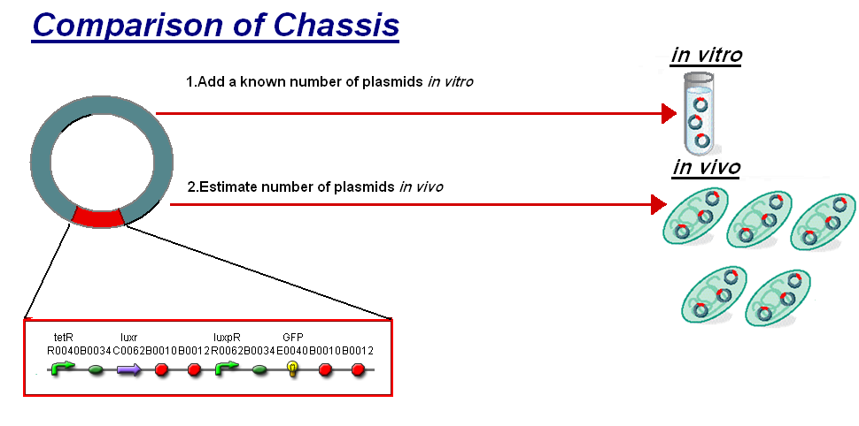
We thought to compare our in vitro characterisation to the characterisation of [http://partsregistry.org/Part:BBa_F2620 F2620] in vivo with the aim to highlight some of the differences between the chassis and investigate how the construct's characteristics may change between them. The [http://partsregistry.org/Part:BBa_F2620 F2620] is an ideal construct for comparison because of its detailed characterisation in vivo. The construct is the same as the construct 1 that was used for infecter detector, pTet-LuxR-pLux-GFPmut3b.
The key results of the comparison were:
- The creation of a new unit to allow comparison between in vitro and in vivo chassis.
- The response of the construct in E.coli chassis in vivo and in vitro is independent of the chassis
These are exciting findings, revealing the potential for the exploration of new chassis and the ability to use constructs in an exchangeable manner.
 |
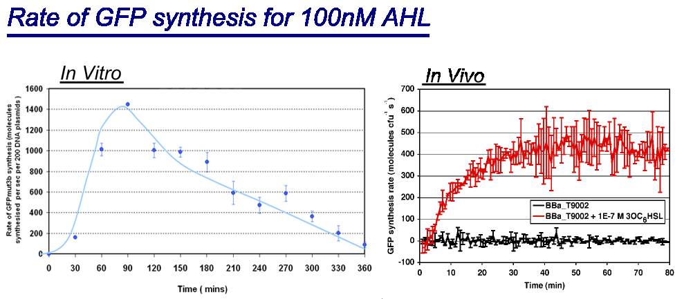
| Comparison between in vivo and in vitro for rate of GFPmut3b synthesis for 100nM AHL. The in vivo chassis used was the bacterial strain MG1655 and the in vitro chassis was Promega Commercial S30 Cell Extract(60µl)
Key Difference:
Interestingly the values of rate of synthesis are in the same order magnitude of hundreds, this suggesting that the normalisation we are using to compare these chassis is valid. |
 |
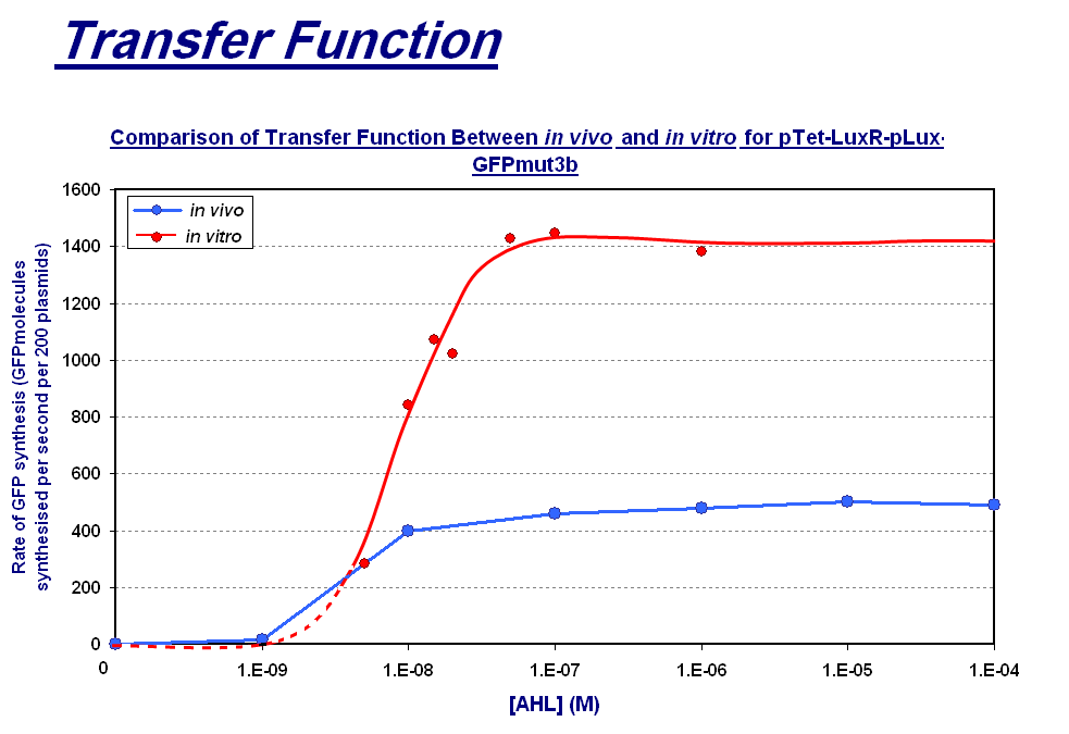
The graph above shows the transfer function of [AHL] input vs rate of GFP synthesis output. The graph shows the follwoing:
|
