Imperial/Infector Detector/Testing
From 2007.igem.org
m (→Materials and Methods) |
|||
| Line 27: | Line 27: | ||
* To determine the steady state response of protein relative to concentration of AHL | * To determine the steady state response of protein relative to concentration of AHL | ||
| - | = | + | =Results= |
| - | = | + | {|align="left" |
| - | + | |<center><br>[[Image:GFPMolecule syn ID2 Final.PNG|500px]]</center> | |
| + | |- | ||
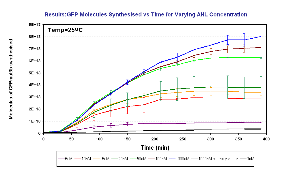
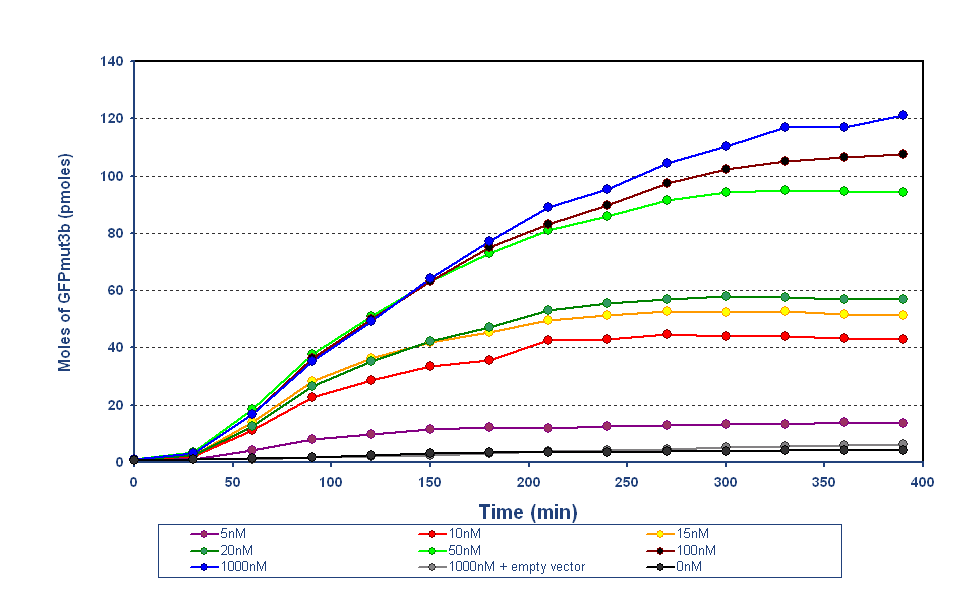
| + | |The results from the final testing are shown in the diagram above, the protocol and results can be found on the following links.... | ||
| + | The fluorescence was converted using our calibration curve, for an explanation see conversion of units page. | ||
| + | The results show us the following: | ||
| + | *The output of '''GFPmut3b increases with input of AHL''' | ||
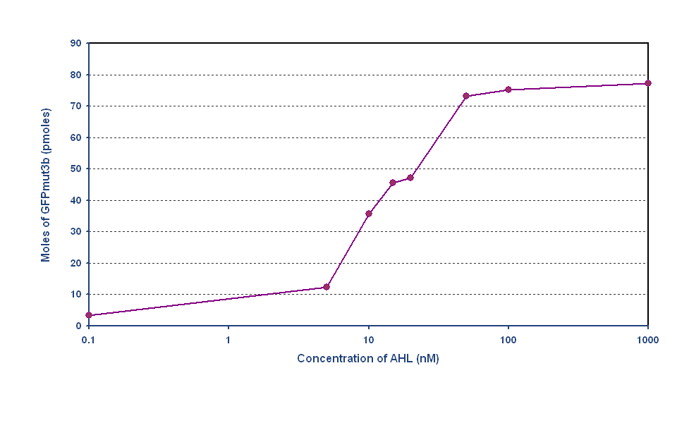
| + | *The system is sensitive to a range of '''5-1000nM AHL''' | ||
| + | *The GFPmut3b molecules synthesis stops at '''~300minutes'''. This could be due to steady state or due to no synthesis of GFPmut3b. It is known not to be steady state because the degradation experiment(link) proved degradation is negligible. Interestingly this time is independent of the GFPmut3b molecules produced, showing that the LuxR under the control of pTet is the major source of energy consumption. This highlights the advantages of using the construct 2 [http://partsregistry.org/Part:BBa_J37032 pLux-GFPmut3b] that does not have the energetic burden of producing LuxR | ||
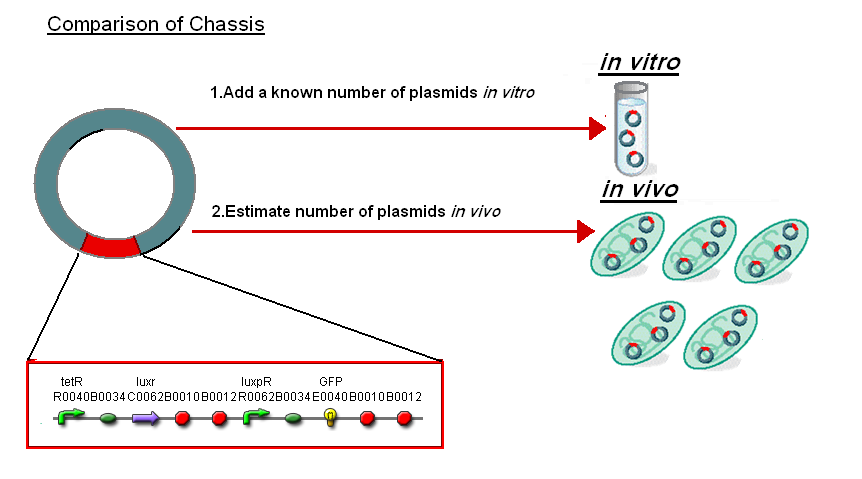
| - | + | In addition the results ''in vitro'' have been compared to the work on [http://partsregistry.org/Part:BBa_F2620 BBa_F2620]('''pTet-LuxR-pLux-GFPmut3b''' ''in vivo'' which is the same as the construct 1 used for infecter detector. To do this we investigated the comparison between ''in vitro'' and ''in vivo.'' | |
| - | + | |} | |
| - | + | <br clear=all> | |
| - | + | {|align="center" | |
| - | + | | width="200px"|<br><center>[[Image:IC2007_,,BF_stage1_construct.PNG|thumb|500px]]</center> | |
| - | + | |} | |
| - | + | ||
| - | + | ||
| - | + | Normalise the in vitro on the plasmids to give a platform for comparison: | |
| - | [ | + | *''In Vitro'' - 4µg of DNA was added which for [http://partsregistry.org/Part:BBa_T9002 '''pTet-LuxR-pLux-GFPmut3b'''] is 904823007 plasmids |
| + | *''In Vivo'' - Each cell has ~30 plasmids per cell | ||
| + | To compare we normalised the data of ''in vitro'' '''GFPmut3b molecules synthesised per 30 plasmids''' to allow some comparison to the ''in vivo'' data. | ||
| + | ===Rate of GFPmut3b Synthesis for 100nM AHL=== | ||
| + | {|align="center" | ||
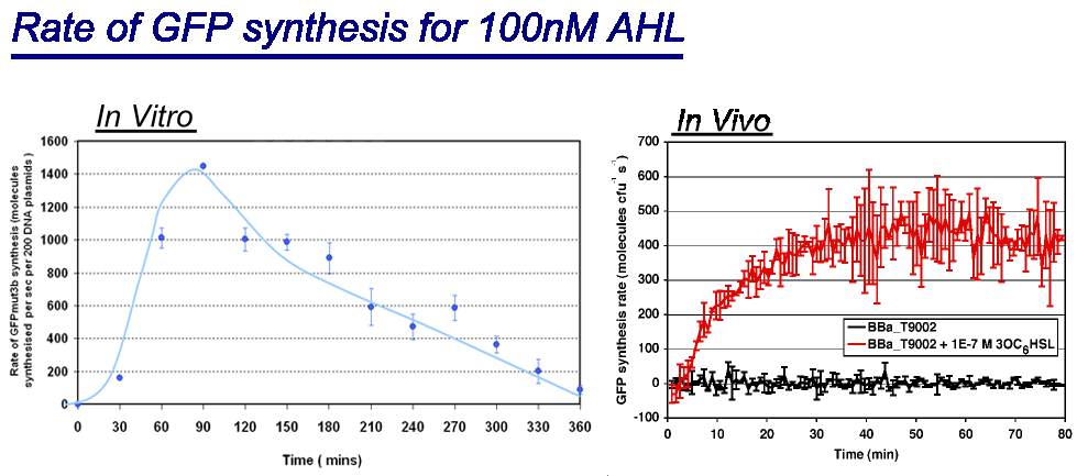
| + | |width="100%"|<br>[[image:In vitro in vivo comp.png|thumb|800px|Comparison between ''in vivo'' and ''in vitro'' for rate of GFPmut3b at 100nM AHL. The rate for in vitro and in vivo was taken for the maximum rate for each chassis. <br> | ||
| + | *''in vivo'' has a maximal rate of 400-500 molecules of GFP synthesised per second per cell. The ''in vivo'' reaches steady state ~30minutes.<br> | ||
| + | *''in vitro'' has the equivalent of 220 molecules of GFP synthesised per second per cell equivalent. This is based upon the normalization on DNA plasmids. The ''in vitro'' chassis decreases in rate of synthesis after 90 minutes and keeps decreasing until rate is zero at around 360 minutes <br> | ||
| + | ]] | ||
| + | |} | ||
| + | |||
| + | ===Transfer Function=== | ||
| + | {|align="center" | ||
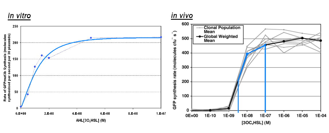
| + | |width="100%"|<br>[[image:In_vivo_in_vitro_comp2.png|thumb|800px|The graph above shows the transfer function of '''AHL input''' vs '''rate of GFP synthesis output'''. The blue line on ''in vivo'' corresponds to the range of AHL on ''in vitro''<br> | ||
| + | *''in vitro'' shows a similar shape to the ''in vivo'' transfer function, however rate of GFP synthesis lower in the ''in vitro'' chassis. e.g. for 1000nM the rate ''in vivo'' is ~450 GFP molecules per sec per cell,'' in vitro has an equivalent value of 220 GFP molecules per second.<br> | ||
| + | *The ''in vitro'' chassis looks as if the rate is very low for low AHL inputs being <10 molecules of GFP per second.]] | ||
| + | |} | ||
| + | |||
| + | ==Summary== | ||
| + | Below is list of which of the orginial Specifications that our infecter detector achieved: | ||
| + | |||
| + | {|border="1" width="80%" align="center" | ||
| + | |- | ||
| + | |width="20%" style="background:#ffffcc"|<center>'''Property'''</center> | ||
| + | |width="--"|<center>'''Value'''</center> | ||
| + | |'''Achievements''' | ||
| + | |- | ||
| + | |style="background:#ffffcc"|Inputs | ||
| + | |<center>System must be sensitive to AHL concentration between 5-50nM</center> | ||
| + | |'''<font color=green>Sensitive to 5-1000nM</font>''' | ||
| + | |- | ||
| + | |style="background:#ffffcc"|Outputs | ||
| + | |<center>System must give a visual signal if bacteria is present</center> | ||
| + | |'''<font color=red>Future work - Using Stronger fluorescent protein such as DsRed express</font>''' | ||
| + | |- | ||
| + | |style="background:#ffffcc"|Response Time | ||
| + | |<center>System needs to have a response time under 3 hour</center> | ||
| + | |'''<font color=green>Systems responds <30minutes</font>''' | ||
| + | |- | ||
| + | |style="background:#ffffcc"|Operating Conditions | ||
| + | |<center>System must operate within temperature 20-30°C</center> | ||
| + | |'''<font color=green>System works at 25°C</font>''' | ||
| + | |- | ||
| + | |style="background:#ffffcc"|Health & Safety | ||
| + | |<center>System Must not be living replicating bacteria, and in any way harmful or infectious.</center> | ||
| + | |'''<font color=green>Cell Free ''in vitro'' chassis</font>''' | ||
| + | |- | ||
| + | |style="background:#ffffcc"|Lifespan | ||
| + | |<center>System must have a shelf life of 7 days</center> | ||
| + | |'''<font color=green>Can be stored in freezer for prolonged periods</font>''' | ||
| + | |- | ||
| + | |style="background:#ffffcc"|Packaging | ||
| + | |<center>System must be portable and convenient to use</center> | ||
| + | |'''<font color=red>Future Work - Using our chassis in a spray</font>''' | ||
| + | |} | ||
| + | <br clear="all"> | ||
== Testing and Results == | == Testing and Results == | ||
Revision as of 10:30, 24 October 2007

Infector Detector: Testing
Aims
The sensitivity of the system is to be determined through this experiment. To do this, we induce the system with known concentrations of AHL. We then record the change in GFP, such that we can calculate the rate of GFP production relative to concentration of AHL in solution.
- To determine the rate of protein production relative to concentration of AHL
- To determine the response time relative to concentration of AHL
- To determine the steady state response of protein relative to concentration of AHL
Results
Normalise the in vitro on the plasmids to give a platform for comparison:
- In Vitro - 4µg of DNA was added which for [http://partsregistry.org/Part:BBa_T9002 pTet-LuxR-pLux-GFPmut3b] is 904823007 plasmids
- In Vivo - Each cell has ~30 plasmids per cell
To compare we normalised the data of in vitro GFPmut3b molecules synthesised per 30 plasmids to allow some comparison to the in vivo data.
Rate of GFPmut3b Synthesis for 100nM AHL
Transfer Function
Summary
Below is list of which of the orginial Specifications that our infecter detector achieved:
| Achievements | ||
| Inputs | Sensitive to 5-1000nM | |
| Outputs | Future work - Using Stronger fluorescent protein such as DsRed express | |
| Response Time | Systems responds <30minutes | |
| Operating Conditions | System works at 25°C | |
| Health & Safety | Cell Free in vitro chassis | |
| Lifespan | Can be stored in freezer for prolonged periods | |
| Packaging | Future Work - Using our chassis in a spray |
Testing and Results
Determine AHL sensitivity
We first induced the system with varying concentrations of AHL to determine the output of the system. From the results, we were able to determine that the sensitivity range of the system was indeed between 5-50 nM, which is what was specified earlier. We can thus calibrate the system to give a visual output at this range of AHL concentrations.
